With 400V on anode don't be afraid to connect G2 directly to anode. It is not voltage that damages the screen grid, it is power. When voltage on the screen grid is fixed and voltage on anode goes down screen grid starts pulling more current and can be overheated and damaged. But when it is tied to anode it is safe to drive both anode and g2 up to 800 volts, in this case you have to watch for anode dissipation that must not go beyond 40 Watt. However, due to material used for anode it can dissipate 100+ watt shortly, but you can't run it in such regime for a long time.
Wavebourn,
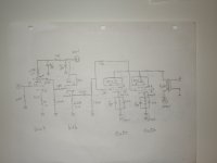
Thanks for your advice. I've made correction on the schematic. Please take a look and comment.
Do I have to care ground the pin 7 ??
Will the drivers work fine ?? anything make change to improve ??
Albert
Attachments
Wavebourn,
Thanks for your advice. I've made correction on the schematic. Please take a look and comment.
Do I have to care ground the pin 7 ??
Will the drivers work fine ?? anything make change to improve ??
It looks fine. Pin 7 is screen between electrodes, it is better to ground it. Also, you may keep that resistors in screen grids as stoppers to avoid possible HF oscillations.
Both Sergeev's and Globulator's schematics look nice.
Oops... I meant Artosalo's schematic that Globulator commented, sorry.
right handed triode mode
Hey,
Haven´t heard that expression before.
Globulator uses a tetrode in anodefollowermode(Schade) with Zin of ca 5k.
Hello
May I ask why you use 6V6 as a driver. 6V6 mostly used as a power tube, I don't say it cant be used as a driver. I sow schematics were 300B drive GM70 tube but extra $$$..
I think 6SN7 if used both side can drive one chanel (two GU50) probably would sound better.
I would be interested on that.
Wavebourn has some schematic if I remember with out coupling caps. That would be very interesting unfortunately was not tested yet.
Greetings Gabor
Hey,
Haven´t heard that expression before.
Like 811, when grid is driven positively, when you connect all grids together.
www.wavebourn.com • View topic - GU-50 Single Ended Amplifier Design
It looks fine. Pin 7 is screen between electrodes, it is better to ground it. Also, you may keep that resistors in screen grids as stoppers to avoid possible HF oscillations.
Wavebourn,
So I join pin 1 & 7 together and through the resistor to ground. Am I correct ???
Albert
So I join pin 1 & 7 together and through the resistor to ground. Am I correct ???
Right.
I'm not sure that the CF will pull 20mA in this configuration. At 20mA the voltage over the cathode resistor would be 44v (20mA x 2k2) and the 6V6 will cut off..
My bad, I did not mention that.

Of course, the amp would be very suboptimal. But punched holes for tube sockets will be a good step ahead. After discovery that voltage swing is not enough to drive Gu-50 he would think how to improve things. I assume from this point real understanding would sprang, leading to first hand experience. However I taught Pascal language on chalkboard simulating response, but it was because hardware was not available then. Curiosity is the thing that drives us to explore details. "Why it happened?" is better question than "Is it perfect?" Nothing is perfect. But as soon as I start feeling of character and behavior of some active component, schematic diagram, I started getting control on it. Sometimes the first step is the hardest one, "How to start?" Actually, it boils down to, "If I start it this way, how close it will be to the perfect solution"? This question stops my projects often, putting brain in endless loops. That's why I have so many unfinished projects. And it would be much better if somebody encourages me, "Do it, try, measure, ask, and we'll help to improve".
You know, what stops my further learning, my experiments? Internal dialogue: "Wait, what if it is not perfect yet?"
But it is a good point, to work on a driver. How much voltage and current swing we want from it, then how to implement it.
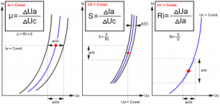
Waveborn, two questions please. It seems counter-intuitive to me. If G2 is pulled so low it should compress the curves and reduce Gm substantually.
1) Does not tying G2 and G3 to G1 at such a low voltage reduce the tube Gm considerably?
2) Is this effective with Tetrodes as well as Pentodes, or is G3 necessary for this to function?
1) Does not tying G2 and G3 to G1 at such a low voltage reduce the tube Gm considerably?
2) Is this effective with Tetrodes as well as Pentodes, or is G3 necessary for this to function?
Waveborn, two questions please. It seems counter-intuitive to me. If G2 is pulled so low it should compress the curves and reduce Gm substantually.
1) Does not tying G2 and G3 to G1 at such a low voltage reduce the tube Gm considerably?
2) Is this effective with Tetrodes as well as Pentodes, or is G3 necessary for this to function?
I have the gut feeling you have all answers. Let's discuss them.
Hmmm...
I think the answer to 1 will answer 2.
I'll have to think about this a while.
G3 is designed to be electrically far from the anode so there is no issue there with excessive dissipation. It is there to shield the effects of G2 which is designed to function as a control grid albeit at a much higher voltage than G1.
The Kinkless Tetrode used beam forming plates to concentrate an electron cloud to do the same function as the third grid in a pentode (prevent secondary emission from the anode).
I just realized you are talking about positive bias on the elements, not A2 with negative bias and excursions into positive bias.
I just realized you are talking about positive bias on the elements, not A2 with negative bias and excursions into positive bias.
Using a 6V6 as CF before the GU50 is wasted when not directcoupling it like Artosalo did. Also a 6SN7 will not have gain enough as single driver.
If going for a pentode input it should be with something more linear and high-Gm than the 6AU6.
Lars,
Thanks for the suggestions. If I could replace the front end with a Mullard CV5311. I thought that will be better - gain wise. I have some 6au6 too, why a 6au6 can do a better job here ??
Albert
My bad, I did not mention that.
Of course, the amp would be very suboptimal. But punched holes for tube sockets will be a good step ahead. After discovery that voltage swing is not enough to drive Gu-50 he would think how to improve things. I assume from this point real understanding would sprang, leading to first hand experience. However I taught Pascal language on chalkboard simulating response, but it was because hardware was not available then. Curiosity is the thing that drives us to explore details. "Why it happened?" is better question than "Is it perfect?" Nothing is perfect. But as soon as I start feeling of character and behavior of some active component, schematic diagram, I started getting control on it. Sometimes the first step is the hardest one, "How to start?" Actually, it boils down to, "If I start it this way, how close it will be to the perfect solution"? This question stops my projects often, putting brain in endless loops. That's why I have so many unfinished projects. And it would be much better if somebody encourages me, "Do it, try, measure, ask, and we'll help to improve".
You know, what stops my further learning, my experiments? Internal dialogue: "Wait, what if it is not perfect yet?"
But it is a good point, to work on a driver. How much voltage and current swing we want from it, then how to implement it.
Wavebourn,
Thanks so much and I love your attitude on teaching people patiently, step by step. And your time to answer all those newbie like me.
I did the same thing when I was an inspector and from time to time to tell people how to build houses. Improvement is something after you know the first step. I know I'll learn something from you, but one at a time.
Thanks again
Albert
- Status
- This old topic is closed. If you want to reopen this topic, contact a moderator using the "Report Post" button.
- Home
- Amplifiers
- Tubes / Valves
- Help with these Russian GU50 tube amplifier