Hello Globulator
Thanks for the answer!
OK if you have the knowledge to design your own in that case go for it.
May be you can give me some advice to.
I plan to use 2 GU50 paralleled, each biased around 90mA. So for the two chanel I need at least 400mA transformer to the plate.
That is correct? Last few month I didn't found power transformer to get 420DCV and min 400mA on Ebay.
Otherwise I have to go with two power transformer. After if I have the two power transformer why not build a mono block.. Need two choke so on....
On the end all cost twice as much I planed to spend on these amp.
Honestly I build these amp to get back into the tube world. All do I read these is a great tube to in a good circuit so if I build something I want to have some value.
Last 15 years I just upgrade tube amp but I didn't built not one.
Just Solid S amps.
After I want to build a GM70.
Actually I wanted only that amp, I collected the parts for that to(but that is to dangerous to start) 1KV to get at least 30W.
My friends told me start with something smaller (lower voltage, not like 400V is so safe)
to have some success and experience.
Greetings Gabor
Ha yes - GM70 is a very difficult tube to use in audio, the impedance is too high.
So for GU50, the transformers you need can either be:
a) Bought from Edcor and shipped to you
b) Found in a cheap chinese amp of roughly the right size.
I chose (b) as I did not realise I could get (a) to the UK, so next time I'll just choose (a). People on the forum can advise the correct transformer, but it's basically a case of matching the voltage a current you have to the speaker.
At least following (b) I ended up with two power transformers, two OTPs and a chassis
")
I'd recommend 50mA idle at 400V for the GU50, and not that much more.
That gives you a ball-park figure of 400/0.05 = 8k for the primary, but I'm a novice at picking transformers.
Why do you want parallel GU50 - one is very powerful!
Do you want to build a PP (Push Pull) or an SE (Single Ended)? Single ended is a LOT simpler TBH, but you need the correct transformers.
As for designing - I'm not sure I have the knowledge but I know what I want to achieve, so I just spend the time figuring out a way to get there - in this case it's a PP amp with GU50 in pentode mode with floating G3, no loop feedback but as much as I can get of local feedback, ideally with as few capacitors as possible. Oh and a proper phase splitter - which means a BDT.
The feedback would be easy with a capacitor - I used a 22uF bypassed one in my SE, but capacitors are dreadful things and must be eliminated
.This site has some interesting info Gegentakt-Verstärker in AB-Betrieb fuer GU 50
Hello
Thank you very much.
I'm interested only on SE triode mode with these tube, 2 stage.
Someone built a SE and a PP with these tubes.
He only kept the SE amplifier. I think even with one tube I can get enough power to drive my speaker.
I will see if I do not get the right power transformer I go with one tube..
Greetings Gabor
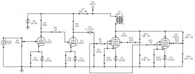
GU50 sounds much better in pentode then in triode. I have build several prototyps one of them is:
http://www.diyaudio.com/forums/tubes-valves/204148-my-little-se-gu50-2.html
First I run in tride - than I change to pentode - I put around 250-255V to grid2 and connect grid3 to Catode. Now it sounds much better. The mids and highs are noticeably better. I bias the GU50 0n around 50ma.
The last project I build is PSE version: ECC81 in SRPP (with B+ around 400V) and Rk 380Ohm - Interstage cap (jantzen Audio Superior) and negative bias for GU50. I set Bias to around 45mA for each tube. The OPT is custom build from my friend - 3500 primary and 8 seconday. I get around 20W of clean power and frequency response from 10Hz to 45KHz. Without any feedback.
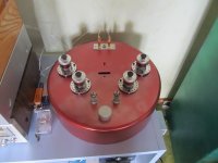
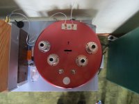
Some pictures of my last prototype: (I move power trany from top to external case because of hum it produced)
http://www.diyaudio.com/forums/tubes-valves/204148-my-little-se-gu50-2.html
First I run in tride - than I change to pentode - I put around 250-255V to grid2 and connect grid3 to Catode. Now it sounds much better. The mids and highs are noticeably better. I bias the GU50 0n around 50ma.
The last project I build is PSE version: ECC81 in SRPP (with B+ around 400V) and Rk 380Ohm - Interstage cap (jantzen Audio Superior) and negative bias for GU50. I set Bias to around 45mA for each tube. The OPT is custom build from my friend - 3500 primary and 8 seconday. I get around 20W of clean power and frequency response from 10Hz to 45KHz. Without any feedback.
Some pictures of my last prototype: (I move power trany from top to external case because of hum it produced)
Attachments
Hello
Thank you very much!
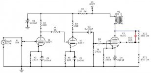
What do you think about these schematic. I like these a lot.
I can give you the website if you interested.
Ãëàâíàÿ ñòðàíèöà.
He get 7W high quality sound with one tube and 14W with two GU50!
Al do I would like to see the parallel GU50 schematic you built for your friend..
Greetings Gabor
Thank you very much!
What do you think about these schematic. I like these a lot.
I can give you the website if you interested.
Ãëàâíàÿ ñòðàíèöà.
He get 7W high quality sound with one tube and 14W with two GU50!
Al do I would like to see the parallel GU50 schematic you built for your friend..
Greetings Gabor
Attachments


Last edited:
Here is my construction. It gives 15 W with low distortion.
This circuit works well with 811A and 807 as well. All connected as hi-mu triode (g2+g1 together) and in class A2.
This circuit works well with 811A and 807 as well. All connected as hi-mu triode (g2+g1 together) and in class A2.
An externally hosted image should be here but it was not working when we last tested it.
This site has some interesting info Gegentakt-Verstärker in AB-Betrieb fuer GU 50
Interesting build!
Very odd time-constant on the GU50 bias circuit though - a 0.1uF capacitor feeding into a 25k (ish) bias circuit, I wonder if they get much bass below 400Hz?
Also the PCB gaps for 400+ volts isolation look a bit optimistic to me.
Looks like the SRS 552N is the beautiful sister version of the GU50, still cheap but quite rare. Didn't know that existed at all..
Here is my construction. It gives 15 W with low distortion.
This circuit works well with 811A and 807 as well. All connected as hi-mu triode (g2+g1 together) and in class A2.
An externally hosted image should be here but it was not working when we last tested it.
Very neat design. Smart idea to ditch the two triode stage to use a pentode - eliminating a coupling capacitor.
You mean the direct connection between 6N6P cathode and GU50 grid ?
GU50 needs 6 to 8 V positive bias voltage and draws grid current too. Some 8 to 10 mA at idle.
6N6P will supply this, so DC-connection is a must.
If I built this today today, I would replace 6N6P with some NFET, IRF-820 or similar.
GU50 needs 6 to 8 V positive bias voltage and draws grid current too. Some 8 to 10 mA at idle.
6N6P will supply this, so DC-connection is a must.
If I built this today today, I would replace 6N6P with some NFET, IRF-820 or similar.
Hello
Thank you very much!
What do you think about these schematic. I like these a lot.
I can give you the website if you interested.
Ãëàâíàÿ ñòðàíèöà.
He get 7W high quality sound with one tube and 14W with two GU50!
Al do I would like to see the parallel GU50 schematic you built for your friend..
Greetings Gabor
What is the primary impedance of the OPT ?
You mean the direct connection between 6N6P cathode and GU50 grid ?
GU50 needs 6 to 8 V positive bias voltage and draws grid current too. Some 8 to 10 mA at idle.
6N6P will supply this, so DC-connection is a must.
If I built this today today, I would replace 6N6P with some NFET, IRF-820 or similar.
No I meant that in my integrated amps I need two gain stages in front of the GU50, but you have used a pentode instead
.The CF/SF is a good idea for A2, and very easy for the previous stage to drive but a mosfet is tempting yes. The GU50 takes a lot of grid current - I guess that's because G1 and G2 are both driven?
Hello
Thank you very much!
What do you think about these schematic. I like these a lot.
I can give you the website if you interested.
Ãëàâíàÿ ñòðàíèöà.
He get 7W high quality sound with one tube and 14W with two GU50!
Al do I would like to see the parallel GU50 schematic you built for your friend..
Greetings Gabor
The first schematic was my inspiration. I want to build my own design. I test for driver D3A tube (in triode mode) with B+ 400V, Anode resistor of 23,7K and Catode resistor of 100R (I am not sure - I never write what I use). It sound excellent. Than I test 6C3P with the same Anode resistor of 23,7K and Catode resistor of 270R. It also sound excelent and finaly I test ECC801S in SRPP mode and I leave my telefunken ECC801S in the amps and now I am developing PushPull.
I took that first schematic and I change:
- the driver section (I use different tubes)
- the interstage caps I use JA Superior 0,22uF (one of my favorite)
- on the GU50 I connect the 3 grid to catode and I put to second about 250V
- my OPT have 3500 Ohm primary (very good build) and 8 Ohm secondary
- my PS is build from 100uF (first cap) - chocke (1,5H) - 1200uF (second cap)
- the only thing I should change is power trany - because of hum or I should build external power supply
Hello Jaap
The reason I didn't purchased the OP transformers because it is still a mystery if I use 1 power tube or 2 in parallel.
Now if I use one I chose 3K OP transformer primery. If I get the right power transformer with out spending a arm and a leg I think 2.2 or 2.5 will do the job.
In case if I order from Edcore and they have 25W 2.2K I will pick that.
Almost I forget I have several D3a tubes at hand now..
Greetings Gabor
Last edited:
Can I use these transformer for ............
Hello
Can I use these transformer for parallel (each channel 2 tube) GU50 plate supply?
325V 250mA POWER TRANSFORMER for TUBE AMP AMPLIFIER HAM RADIO KT88 EL34 6L6 | eBay
Please let me know.
Thank you very much.
I know I need another transformer for the bias but what can I do.
I ask because these local sale and the shipping does not cost $$$...
Even if I can use it for 1 tube each chanel I would be interested on it. If (the online translation from Russian to English was correct)I understood the power tube biased close to 100mA..
Îäíîòàêòíûé óñèëèòåëü íà ÃÓ-50
Please take a look and if you can help me please.
Thank you
Greetings Gabor
Attachments
Hello
I got that transformer from EPay, all do will give higher anode voltage than 420V I will see what can start with.
If I can get from 1 power tube 7W clear power that would be enough.
I have the sockets and tubes for parallel set up to but with these transformer I can"t go 90mA/tube.
Also I read octal tube as a driver like 6SN7 would be better choice. Actually I have both driver tube at hand any advise, experience welcome!
Here I found a schematic with that driver tube but I have to study what I can do with my power transformer.. I have a 6H 200mA choke I want to use that for these project.
Also I have a 12VAC 5A transformer and 12VDC 2A PS for heater.
I don't think I need to bias the power tubes to the max to get the best performance.
If you can help me which way to go from here with advice etc so I can purchase the right OP transformers.
Thank you very much!
Greetings Gabor
Attachments
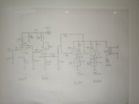
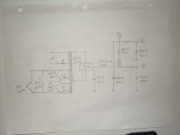
PSE
Hi,
Being a copy cat for too long and now I want to try out something with I have learnt. Since I have all the parts in the schematic below and try to build something from scratch. All numbers in the schematic are what I'm aiming at. Please do give valuable comment and see if the design would work or not
Thanks
Albert
I only hand draw the schematic and hope you'll see it.
Attachments
With 400V on anode don't be afraid to connect G2 directly to anode. It is not voltage that damages the screen grid, it is power. When voltage on the screen grid is fixed and voltage on anode goes down screen grid starts pulling more current and can be overheated and damaged. But when it is tied to anode it is safe to drive both anode and g2 up to 800 volts, in this case you have to watch for anode dissipation that must not go beyond 40 Watt. However, due to material used for anode it can dissipate 100+ watt shortly, but you can't run it in such regime for a long time.
Last edited:
Hello
Thank you Wavebourn!
I tried to contact with the guy who posted the schematic I didn't got answer from him.
I think the best I can do to buy a pair OP transformer around 3K primery 15-20W, I can use that with 2 tube parallel or with one tube also.
Thanks one more time.
Greetings Gabor
Thank you Wavebourn!
I tried to contact with the guy who posted the schematic I didn't got answer from him.
I think the best I can do to buy a pair OP transformer around 3K primery 15-20W, I can use that with 2 tube parallel or with one tube also.
Thanks one more time.
Greetings Gabor
You are welcome Gabor!
Both Sergeev's and Globulator's schematics look nice. First one uses Gu-50 in triode mode, second one in right handed triode mode. Last year I started a project with paralleled Gu-50 for 25-30W output, but postponed it for some time. I can't promise something certain, but I will definitely continue the project. The idea is Gu-50 tubes in right handed mode, with parallel feedback by voltage across them. I don't want to give some theoretical, raw ideas, I want to test everything practically before giving some advises, as I usually do.
Both Sergeev's and Globulator's schematics look nice. First one uses Gu-50 in triode mode, second one in right handed triode mode. Last year I started a project with paralleled Gu-50 for 25-30W output, but postponed it for some time. I can't promise something certain, but I will definitely continue the project. The idea is Gu-50 tubes in right handed mode, with parallel feedback by voltage across them. I don't want to give some theoretical, raw ideas, I want to test everything practically before giving some advises, as I usually do.
- Status
- This old topic is closed. If you want to reopen this topic, contact a moderator using the "Report Post" button.
- Home
- Amplifiers
- Tubes / Valves
- Help with these Russian GU50 tube amplifier