Hi hitachi_nut,
yes you were the first who suggested capacitor leakage issue and for that you deserve all credit and my gratitude.
")
My only fear is that not only caps are the culprits here. Only reason for me thinking that way is because the amp was silent for more then six months after recapping, if the caps were leaking wouldn't they leak from beginning, such was the case with C517, it leaked the most when freshly installed.
Anyways, per your recommendation I ordered Panasonic caps ECQV1 in 1uF/63V value so we can exchange C505/C506 and C527/C528, I recall you mentioned they are small in size, do you perhaps know exactly how small, those MKT were a tight fit so just to know what to expect when Panasonics arrive.
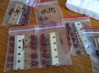
My wife informed me that the Panasonic caps finally arrived, contrary to my expectations they arrived last although the were ordered first. That is life
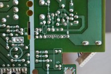
My wife was also kind enough to send me this picture, I am at work, so in preparation to install them I have a few questions. From the picture it looks like lead space is pretty wide, Mooly you suggested drilling the pcb instead of bending the leads. Since I have never done such a thing I practiced a little on some pcb pictured below. I understand I should expose bare copper but how do I improvise the "eyelet", soldering post that is. Track in the picture is pretty wide so "eyelet" in this case is probably unnecessary, but I presume that the tracks in my amplifier are probably thinner. Inputs very welcomed here.
, contrary to my expectations they arrived last although the were ordered first. That is lifeMy wife was also kind enough to send me this picture, I am at work, so in preparation to install them I have a few questions. From the picture it looks like lead space is pretty wide, Mooly you suggested drilling the pcb instead of bending the leads. Since I have never done such a thing I practiced a little on some pcb pictured below. I understand I should expose bare copper but how do I improvise the "eyelet", soldering post that is. Track in the picture is pretty wide so "eyelet" in this case is probably unnecessary, but I presume that the tracks in my amplifier are probably thinner. Inputs very welcomed here
.Attachments
Gently scrape off the coating over the copper strip.
Apply a hot iron and cored solder to the freshly cleaned copper surface to thinly tin the strip with the holes.
Insert the legged components from the other side.
Solder each components leg to it's respective strip (pad).
Apply a hot iron and cored solder to the freshly cleaned copper surface to thinly tin the strip with the holes.
Insert the legged components from the other side.
Solder each components leg to it's respective strip (pad).
Gently scrape off the coating over the copper strip.
Apply a hot iron and cored solder to the freshly cleaned copper surface to thinly tin the strip with the holes.
Insert the legged components from the other side.
Solder each components leg to it's respective strip (pad).
Hi AndrewT,
and thanks for quick reply. So I should carefully tin around the hole before inserting the cap? One more, I presume I can but just to be sure, can I use one original existing hole and add another, new one which is drilled further apart then the second original hole? It is a complicated sentence
but I think you will understand what I mean.your newly drilled holes are quite close together. Just tin the whole strip. Don't try to create a tinned pad around each hole.
If you had a single isolated hole, then it is worth exposing a small clean copper area to create a single pad.
Soldering the pad areas (strip) before you attempt to attach the components will make the attachment much easier and less likely to damage the components and less likely to damage the glue joint from copper to substrate.
The green solder resist just scrapes off. Try a sharp craft knife.
If the tracks in the amp are very thin then to avoid damage drill the hole next to the track without actually drilling into the copper. Then scrape the resist from the track alongside and insert the component lead and bend it to the newly cleaned track and solder.
If the tracks in the amp are very thin then to avoid damage drill the hole next to the track without actually drilling into the copper. Then scrape the resist from the track alongside and insert the component lead and bend it to the newly cleaned track and solder.
I sincerely hope this is the end of LN cap replacement
Your not the only one
Just in case with those wimas I also ordered some tantalums 3,3uf for C545,C546 position, if the need arise
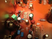
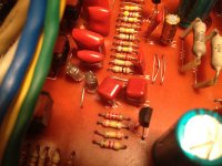
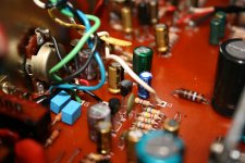
they are at hand.The caps were a lot smaller in person then the picture suggested and the color of them is such that they blended perfectly in the Rotel interior, thanks for recommendation hitachi_nut, unfortunately same can not be said for those light green MKT caps, see pictures.
I drilled new holes the for leads and that went smoothly, although I would like to add one more advice to those already made by AndrewT and Mooly, and that is to check for any resistor crossing the track to be drilled on the top side, I was lucky
To summarize C505/506 and C527/C528 have been changed to Panasonic ECQV 1uF, C517/C518 to ERO VISHAY MKT1826 4.7uF. Everything that was unsoldered before for testing purposes is soldered back, except of course volume pot and C505 and C506 are still tied to ground via point E7.
Is it (tea) pot time now?
, unfortunately same can not be said for those light green MKT caps, see pictures.I drilled new holes the for leads and that went smoothly, although I would like to add one more advice to those already made by AndrewT and Mooly, and that is to check for any resistor crossing the track to be drilled on the top side, I was lucky
To summarize C505/506 and C527/C528 have been changed to Panasonic ECQV 1uF, C517/C518 to ERO VISHAY MKT1826 4.7uF. Everything that was unsoldered before for testing purposes is soldered back, except of course volume pot and C505 and C506 are still tied to ground via point E7.
Is it (tea) pot time now?
Attachments
So the amp should be silent... yes... of course it is
So wiring the volume control is next. One step and one channel at a time.
I would connect the volume control grounds (both channels for this) correctly to the PCB. That is the E4 to E7 connection which goes to BOTH ground terminals on the pot.
Leave C505 shorted for the moment.
Connect C506 to the volume pot wiper. Thats connection "12" and "18".
Leave the input to the pot open for now.
The amp should be quiet now on this channel as the volume control is turned.
If that is OK then connect C505 to the other wiper on the pot still leaving the inputs to the pot open.
The pot should still be silent now on both channels as it is turned.
If we are good up to here we now connect the inputs to the pot and test the whole amp.
So the amp should be silent... yes... of course it is
So wiring the volume control is next. One step and one channel at a time.
I would connect the volume control grounds (both channels for this) correctly to the PCB. That is the E4 to E7 connection which goes to BOTH ground terminals on the pot.
Leave C505 shorted for the moment.
Connect C506 to the volume pot wiper. Thats connection "12" and "18".
Leave the input to the pot open for now.
The amp should be quiet now on this channel as the volume control is turned.
If that is OK then connect C505 to the other wiper on the pot still leaving the inputs to the pot open.
The pot should still be silent now on both channels as it is turned.
If we are good up to here we now connect the inputs to the pot and test the whole amp.
You mean silent while operating low filter switch? I must admit I haven't tried that yesterday but if it is noisy again I am ready to throw in the towel and raise the white flag, so for the benefit of my mental health lets just assume that it is indeed silent
Couple of questions:
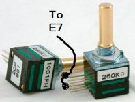
-which volume pot do you want to be installed, the old original one or new TKD (my personal preference is TKD as I can not imagine going back to poor left/right tracking of the old pot after hearing TKD)
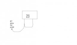
-the original volume pot had only ONE ground connection, that is to E7, look at the picture. I wired new pot which has TWO ground connections like in the second picture
Attachments

Run two separate grounds from the vol pot. For stereo, there will be 4 ground wires at the vol pot.
Treat each channel separately.
The input signal is two wires. Run them between RCA input socket and vol pot.
The output from the vol pot is two wires. Run these between the vol pot and the input pads of the amplifier.
Repeat exactly for the other channel.
Now there is a problem with what I have just described and that problem has alternative solutions. Neither is perfect. So try each and choose the one that seems to be or measures better.
Twist each pair of wires. This minimises interference pick up. It will also minimise crosstalk.
Run the two channels of input wires close together. This increases HF crosstalk, but minimises the hum loop of the dual input channels.
Now choose.
Check that the signal returns (the ground half of each of these signal pairs) is not connected to the Main Audio Ground.
Ground the pair of input RCAs to the Main Audio Ground.
This grounding wire should follow the route of the signal pairs to the vol pot and continue following the signal pair to the amp input pads. And then the grounding wire goes to the Main Audio Ground.
Or
Ground the amplifier input pads to the Main Audio Ground.
Do not ground both ends of that input signal pair.
Measure the amplifier hum using both methods.
Last edited:
I am ask twice-solder once kind of guy, so couple more questions if you can bear with me.
Do you both agree that version A is better than version B?
If version A is the way to go I will have to use thinner wires, is one twisted pair from UTP (network) cable suitable for this application?
I am also enclosing a picture of original wiring, you can see from the picture that all wires going to and from the pot were loosely twisted around each other.
Thank you very much for your answers
Marko
Attachments
Your original pot is here,
http://www.diyaudio.com/forums/solid-state/202909-help-dc-volume-pot-3.html#post2832789
I would fit the new one and wire the two ground pins together at the pot and run a single wire back to the PCB preserving the original scheme.
Like this
http://www.diyaudio.com/forums/solid-state/202909-help-dc-volume-pot-3.html#post2832789
I would fit the new one and wire the two ground pins together at the pot and run a single wire back to the PCB preserving the original scheme.
Like this
Attachments
Mooly,
that's where we disagree.
I believe in twisted pair of signal hot with signal return.
If you create a signal ground star at the vol pot then you force the signal returns to follow a different route from the signal hots. That creates a loop area in the signal wiring.
that's where we disagree.
I believe in twisted pair of signal hot with signal return.
If you create a signal ground star at the vol pot then you force the signal returns to follow a different route from the signal hots. That creates a loop area in the signal wiring.
Hi Andrew,
My reasoning is that without first hand knowledge of the amp i.e. in front of me on the bench, then using the original manufacturer scheme seems the safest option.
If you meant a separate ground wire per gang on the pot, and that twisted with the wiper connection for that gang then that is an alternative way even though both grounds end up at point E7
I didn't quite follow this part as it's an integrated amp.
Quote "The input signal is two wires. Run them between RCA input socket and vol pot."
That would add another ground run in "parallel" to what is already there.
Maybe draw out what you mean... but I think sticking to the original layout is best here.
Attachments
So the amp should be silent... yes... of course it is
So wiring the volume control is next. One step and one channel at a time.
I would connect the volume control grounds (both channels for this) correctly to the PCB. That is the E4 to E7 connection which goes to BOTH ground terminals on the pot.
Leave C505 shorted for the moment.
Connect C506 to the volume pot wiper. Thats connection "12" and "18".
Leave the input to the pot open for now.
The amp should be quiet now on this channel as the volume control is turned.
If that is OK then connect C505 to the other wiper on the pot still leaving the inputs to the pot open.
The pot should still be silent now on both channels as it is turned.
If we are good up to here we now connect the inputs to the pot and test the whole amp.
Good news is the amp is still absolutely silent while operating LF switch.
With connecting the pot I did not get very far
, but somehow I expected that.-both pot ground terminals connected to E7 via one wire
-C505 shorted to ground via E7
-C506 (point 12 on PCB) connected to the wiper of the pot
-no pot inputs connected
I get the same sparkling type of noise as before in BOTH channels while rotating the pot, perhaps the noise is stronger in the right channel but the difference if any is subtle. When there is no movement of the pot there is no noise, there is also no noise while rotating if I use any non-conductive material between my hand and the pot shaft, the noise is also lower in intensity if I touch the amp chassis with the other hand.
I was tempted to short C506 back to the ground and try with C505 instead, but I choose rather to report here and wait for further instructions
.To hear a noise in both channels is really strange as we have C505 (input to one channel) shorted.
Can you try this...
unsolder all wires from the pot and then measure on ohms (use a high ohms range as well, one that will show meg ohms) from the chassis to all the leads on the pot.
Do you get any reading ?
Can you try this...
unsolder all wires from the pot and then measure on ohms (use a high ohms range as well, one that will show meg ohms) from the chassis to all the leads on the pot.
Do you get any reading ?
- Status
- This old topic is closed. If you want to reopen this topic, contact a moderator using the "Report Post" button.
- Home
- Amplifiers
- Solid State
- Help with DC on volume pot