Changing C517 to another cap made left, good until then, channel noisy, no doubt about it.
Do you want me to exchange C517 to low leakage type also?
That has to be proof enough doesn't it ? If leakage were not a factor then it would make no difference.
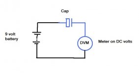
You can try this just for fun. Look at the diagram. The DVM is set to DC voltage and placed in series with the cap as shown. The tiny current drawn by the meter on "volts" is enough to slowly charge the cap. If the cap has zero leakage then the meter should eventually show zero volts.
I used a 12 volt battery. I also read the battery voltage via a 10Megohm resistor to see what load (resistance) the meter was and got around 6.18volts. I think most DVM's should be similar. That means the meter is approximately like a 10M resistor on DC volts and so that is what is "charging" the cap.
I tried it with the 47uF Panasonic cap and got this.
3.35 volts, 15 minutes
2.57 volts, 20 minutes
1.70 volts, 35 minutes
1.49 volts, 40 minutes
1.29 volts, 50 minutes
1.20 volts, 60 minutes
0.80 volts, 2 hours
0.77 volts, 2 hours 15 minutes
A smaller cap will charge quicker of course and have a lower leakage.
Try it and see what you get on any of your caps.
It's not scientific or accurate... it just gives a rough idea.
Attachments
You can also do this.
The cap can be initially charged quickly by "shorting" the meter leads together of course. When you connect the DVM back up, in theory the reading then should be zero volts but in practice it won't be. It will begin to rise. The big question is to what value.
The cap can be initially charged quickly by "shorting" the meter leads together of course. When you connect the DVM back up, in theory the reading then should be zero volts but in practice it won't be. It will begin to rise. The big question is to what value.
You can also do this.
The cap can be initially charged quickly by "shorting" the meter leads together of course. When you connect the DVM back up, in theory the reading then should be zero volts but in practice it won't be. It will begin to rise. The big question is to what value.
I will try this method on all the caps I have, I am wondering what will results show.
Good news is I ordered some film caps in 4.7uF value, bad news is I don't expect them to be here earlier then 2 weeks.
I've left the Panasonic cap charging so I'll see what it finally settles at. Been on 3 hours now.
If you have any of the original LN marked caps it would be worth comparing against those.
If you try this with a film cap then the DC voltage reading should be virtually zero.
If you have any of the original LN marked caps it would be worth comparing against those.
If you try this with a film cap then the DC voltage reading should be virtually zero.
I've left the Panasonic cap charging so I'll see what it finally settles at. Been on 3 hours now.
If you have any of the original LN marked caps it would be worth comparing against those.
If you try this with a film cap then the DC voltage reading should be virtually zero.
Yes, I had that same thought, unfortunately I junked the old caps. I am sorry now I did, however the difference between caps that made left channel silent and these new ones on which it pops would be interesting as well.
I haven't been able to find much out about the original LN marked caps
And just for interest...
The cap in the above test ended up at reading 0.480 volts after 7.5 hours. I then discharged the cap (via a resistor to be gentle) and put it back on test again. After 1 hour the voltage was already down to 0.57v. So it seems that the cap does behave differently after fully forming. The leakage must be lower. What it would be like a week or a month later is anyones guess.
Every manufacturer (that I have found so far) that gives data for checking the specification of their electrolytics also states that the DUT must be reformed before the testing and gives a maximum time limit between end of reforming and start of testing, <24hrs.
Reforming seems to be critical to getting consistent results.
Reforming seems to be critical to getting consistent results.
Every manufacturer (that I have found so far) that gives data for checking the specification of their electrolytics also states that the DUT must be reformed before the testing and gives a maximum time limit between end of reforming and start of testing, <24hrs.
Reforming seems to be critical to getting consistent results.
Thanks Andrew.
This (reforming) is a subject I have never really looked into... not the ins and outs of it all anyway.
That has to be proof enough doesn't it ? If leakage were not a factor then it would make no difference.
You can try this just for fun. Look at the diagram. The DVM is set to DC voltage and placed in series with the cap as shown. The tiny current drawn by the meter on "volts" is enough to slowly charge the cap. If the cap has zero leakage then the meter should eventually show zero volts.
I used a 12 volt battery. I also read the battery voltage via a 10Megohm resistor to see what load (resistance) the meter was and got around 6.18volts. I think most DVM's should be similar. That means the meter is approximately like a 10M resistor on DC volts and so that is what is "charging" the cap.
I tried it with the 47uF Panasonic cap and got this.
3.35 volts, 15 minutes
2.57 volts, 20 minutes
1.70 volts, 35 minutes
1.49 volts, 40 minutes
1.29 volts, 50 minutes
1.20 volts, 60 minutes
0.80 volts, 2 hours
0.77 volts, 2 hours 15 minutes
A smaller cap will charge quicker of course and have a lower leakage.
Try it and see what you get on any of your caps.
It's not scientific or accurate... it just gives a rough idea.
I am a lot more optimistic about cap leaking theory, because when I came home from work amp was still on and the noise has diminished substantially. If soldering back Q504 further diminishes noise I can even imagine that channel being silent with current cap in place.
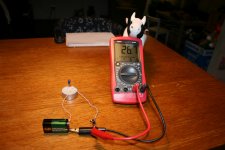
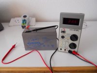
Since I skipped on soldering, I performed battery test on ELNA RLB low leakage type, 1uF 50V. I got way lower reading then you Mooly so I am enclosing a picture for inspection
")
ELNA RLB 1uF 50V on 9V (8.36 actually) battery
15 min. 72mV
30 min. 55mV
45 min. 38.4mV
60 min. 27.8mV
75 min. 24.9mV
90 min. 18.8mV
Attachments
The noise reducing over time does point to a reduction in leakage. Wasn't there another issue of the volume control being "scratchy" when turned ? That points to cap leakage too, C505 and C506.
Connecting the transistors shouldn't really make any difference... but lets check it all one step at a time keeping the test conditions the same.
My test cap was 47uF not 1uF so the leakage and time to charge would be much higher.
I'll see what small value electroylitics I have.
Connecting the transistors shouldn't really make any difference... but lets check it all one step at a time keeping the test conditions the same.
My test cap was 47uF not 1uF so the leakage and time to charge would be much higher.
I'll see what small value electroylitics I have.
The noise reducing over time does point to a reduction in leakage. Wasn't there another issue of the volume control being "scratchy" when turned ? That points to cap leakage too, C505 and C506.
Connecting the transistors shouldn't really make any difference... but lets check it all one step at a time keeping the test conditions the same.
My test cap was 47uF not 1uF so the leakage and time to charge would be much higher.
I'll see what small value electroylitics I have.
Well this morning (amp is now on for 30 hours) I am happy to report that left channel is noise free and right channel gives only a slight pop while operating switch. I was even using headphones this time, which I presume are even more sensitive to noise than the speakers. Looks like Silmic II are not bad caps after all, they just need more burn in time.
I was mentioning Q504 because, if you remeber, when we removed it we had great increase in noise. I am hoping for that same effect in reverse direction this time.
With the transistors removed the DC voltage on the cap increases and that of course increases the leakage and so the noise.
You want a cap that works well from "cold" too. such as the amp being off for a few days.
Leaving the amp on and the noise reducing is proving the theory more and more.
You want a cap that works well from "cold" too. such as the amp being off for a few days.
Leaving the amp on and the noise reducing is proving the theory more and more.
I dispute your conclusion and everyone else that talks about "burning in"...............are not bad caps after all, they just need more burn in time.........
Use capacitors that already meet specification and the operating currents will reach correct levels as soon as the internal temperatures have stabilised to their final design values.
"already meet specification" requires that the every electrolytic capacitor whether it is new or old stock or recycled from an ancient project need to be reformed before putting to use.
I will contend that the "burning in" effect is simply down to using out of specification components that are running at the wrong temperatures combined with the brain re-interpreting the sound waves as time passes it gets used to this "new" sound.
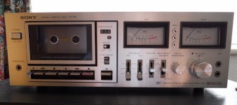
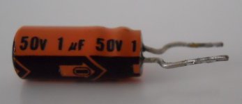
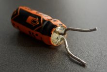
I have an old (1978 vintage) Sony TCK5 cassette deck. Looked at the circuit and sure enough some caps around the tape head preamp and the record level control are marked with an "N". So I had a look and pulled two out. A 4.7uF 25v and a 1uF 50v.
The 4.7uF got down to around 22mv in the same test set up (12 volt battery) in only an hour and this cap has been powered up for months and months. Leakage seems very low to me.
Look also at the construction of the cap. The end where the "rubber bung" is appears to be some kind of hard epoxy.
The 1uF is currently on test...
Attachments
That has to be proof enough doesn't it ? If leakage were not a factor then it would make no difference.
You can try this just for fun. Look at the diagram. The DVM is set to DC voltage and placed in series with the cap as shown. The tiny current drawn by the meter on "volts" is enough to slowly charge the cap. If the cap has zero leakage then the meter should eventually show zero volts.
I used a 12 volt battery. I also read the battery voltage via a 10Megohm resistor to see what load (resistance) the meter was and got around 6.18volts. I think most DVM's should be similar. That means the meter is approximately like a 10M resistor on DC volts and so that is what is "charging" the cap.
I tried it with the 47uF Panasonic cap and got this.
3.35 volts, 15 minutes
2.57 volts, 20 minutes
1.70 volts, 35 minutes
1.49 volts, 40 minutes
1.29 volts, 50 minutes
1.20 volts, 60 minutes
0.80 volts, 2 hours
0.77 volts, 2 hours 15 minutes
A smaller cap will charge quicker of course and have a lower leakage.
Try it and see what you get on any of your caps.
It's not scientific or accurate... it just gives a rough idea.
The only thing you're measuring is the time constant of the RC network you created.
The only thing you're measuring is the time constant of the RC network you created.
Not exactly
If that were so then a 4.7uF film or electroylitic would be identical.
We can get around any time constant just by shorting the meter out (charging the cap to the supply volts). That charges the cap instantly.
The meter theoretically should read zero then... it doesn't, the leakage shows.
The 1uF (N) cap is now down to 18mv.
Well of course the electrolytic is more leaky than a film. The more important question is whether or not that matters in the particular application where you are using them.
I dispute your conclusion and everyone else that talks about "burning in".
Use capacitors that already meet specification and the operating currents will reach correct levels as soon as the internal temperatures have stabilised to their final design values.
"already meet specification" requires that the every electrolytic capacitor whether it is new or old stock or recycled from an ancient project need to be reformed before putting to use.
I will contend that the "burning in" effect is simply down to using out of specification components that are running at the wrong temperatures combined with the brain re-interpreting the sound waves as time passes it gets used to this "new" sound.
Hi AndrewT,
I am sorry we are in dispute
Schematics called for 4.7uF 25V 85C cap and that is exactly what I installed in that place. The LN (low noise) marking, as I looked for replacement caps none were marked as such, some were low-esr and low-leakage, don't know if that equals low noise. It was my presumption, obviously a wrong one, that every modern brand name cap made for audio is low noise cap and equals or betters caps made 30 years ago. And I am betting that 9 out of 10 people with different amp then mine would not have problems with caps I choose for substitutes.
I think Mooly is right about the design of this amp determining such tight leakage specs in caps.
When I mentioned burning in I was not implying that after burning in these caps deliver "precisely tailored frequency response with powerful bass punch, clear mid-range and extended highs" but merely that the popping was louder when they were freshly installed, and after 30 hours noise was drastically reduced.
Anyways, I am already punished for my negligence enough, I soldered every night until late in the evening for almost a month trying to solve this puzzle, and if it wasn't for you guys with great knowledge willing to share it I alone would never establish the cause of popping.
Although it was sometimes exhausting, I am glad I went through all of this, I used a scope for a first time, learned something about electronics, witnessed some great troubleshooting techniques from the experts and I would do it again, no doubt about it.
Thanks
Not exactly
If that were so then a 4.7uF film or electroylitic would be identical.
We can get around any time constant just by shorting the meter out (charging the cap to the supply volts). That charges the cap instantly.
The meter theoretically should read zero then... it doesn't, the leakage shows.
The 1uF (N) cap is now down to 18mv.
My finished at the 5.6mV in the morning.
Well of course the electrolytic is more leaky than a film. The more important question is whether or not that matters in the particular application where you are using them.
It very definitely does in this (The Rotel amp) application.
- Status
- This old topic is closed. If you want to reopen this topic, contact a moderator using the "Report Post" button.
- Home
- Amplifiers
- Solid State
- Help with DC on volume pot