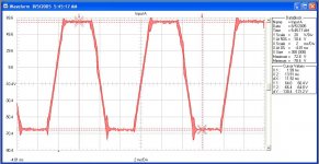
Lastly, here is the filter ripple.
I did the above testing without a load and after about 3 minutes I started smelling something getting warm... I killed power and felt around and the output inductor was smokin' HOT. I couldn't put my finger on it for more than 2 seconds before the heat was unbearable. Why is the inductor getting so hot?
I am using a 47uH torroidal inductor
Part Number = 2309-H [digikey.com]
inductance = 47uH @ 1Khz
Idc = 10.7Amps
resistance = 16milli ohms
I am convinced I am probably just using the wrong type of core material .
Can someone tell me where I can order the right core? Preferably without having to wind my own... [Although I will if necessary]
OD ~ 1.15 inches
ID ~ 0.5 inches
Does anyone have any requests on seeing a scope image of something?
Attachments
Hi,
Might have to play with your deadtime somewhat, either to minimize or increase it, not sure which way you need to go with it. Experiment.
Could explain those spikes you're seeing, most obvious in the filter ripple.
You've done great thus far but you just crossed the "start" line, all the tweaking is ahead, hope you're looking forward to it, expect to burn a few more parts")
Self oscillating amps have some natural frequency modulation as well, and is slower at high modulation index, I"ll let Phase Accurate explain that better.
I'm wondering what you're taking those waveforms with, do you use a PC 'scope?
Anyway, once you start working out the bugs with the dead time I see no harm in at least "trying" to increase frequency.
Sounds like this is for car audio?
I dont' know this amp at all either, it may behave differently when you have a load on it.
Nice effort,
Chris
Might have to play with your deadtime somewhat, either to minimize or increase it, not sure which way you need to go with it. Experiment.
Could explain those spikes you're seeing, most obvious in the filter ripple.
You've done great thus far but you just crossed the "start" line, all the tweaking is ahead, hope you're looking forward to it, expect to burn a few more parts
Self oscillating amps have some natural frequency modulation as well, and is slower at high modulation index, I"ll let Phase Accurate explain that better.
I'm wondering what you're taking those waveforms with, do you use a PC 'scope?
Anyway, once you start working out the bugs with the dead time I see no harm in at least "trying" to increase frequency.
Sounds like this is for car audio?
I dont' know this amp at all either, it may behave differently when you have a load on it.
Nice effort,
Chris
Once my amp was working OK with a micrometals core, I tried to replace it with a very similar inductor, also from JWMiller and also from Digikey, but it was 2305-H (22 uH instead of 47 uH), with the same results as you.
My sw. freq. is around 250KHz and the core got unbearably hot even with no signal. (my old core didn't heat up at all) That's due to the core characteristics, that is not suitable for high frequency.
There's simply nothing you can do with that coil in your amplifier.
My sw. freq. is around 250KHz and the core got unbearably hot even with no signal. (my old core didn't heat up at all) That's due to the core characteristics, that is not suitable for high frequency.
There's simply nothing you can do with that coil in your amplifier.
That's due to the core characteristics, that is not suitable for high frequency.
My assumption is the same as magnetic losses are not only flux-density dependant but frequency-dependant as well.
So you'd have to use a different core material.
I understand that your design is self-oscillating, isn't it ?
Regards
Charles
classd4sure:
I will try increasing and decreasing my deadtime through the gate resistors. Right now it is at 10 ohms but I will try a 4.7ohm for the low end and a 33ohm for the high end.
The waveforms were captured with a fluke 199C handheld DSO.
Yes, this will be for a car amplifier. I am aiming for 500Wx2. I already have the power supply and preamplifier/tone controls built and working.
---------------------
Pierre:
I have a red torroid sitting on my workbench -- I forget exactly where I got it but I think it was a micrometals sample. I will try winding that with 29uH and seeing what happens.
----------------------
phase_accurate:
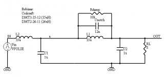
This is a self-oscillating design. I will repost a schematic with the actual parts values I used.
----------------------
I am using IRF644 MOSFETS. Could the carrier spikes seen on the filter output be caused by the body diode?
-=Randy
I will try increasing and decreasing my deadtime through the gate resistors. Right now it is at 10 ohms but I will try a 4.7ohm for the low end and a 33ohm for the high end.
The waveforms were captured with a fluke 199C handheld DSO.
Yes, this will be for a car amplifier. I am aiming for 500Wx2. I already have the power supply and preamplifier/tone controls built and working.
---------------------
Pierre:
I have a red torroid sitting on my workbench -- I forget exactly where I got it but I think it was a micrometals sample. I will try winding that with 29uH and seeing what happens.
----------------------
phase_accurate:
This is a self-oscillating design. I will repost a schematic with the actual parts values I used.
----------------------
I am using IRF644 MOSFETS. Could the carrier spikes seen on the filter output be caused by the body diode?
-=Randy
With carrier-based class-d amps you can sometimes get such spikes when the loop is designed in a suboptimal way. Self oscillating designs are less susceptible to that, but who knows.
But I would also change the core first and check this problem afterwards.
Regards
Charles
But I would also change the core first and check this problem afterwards.
Regards
Charles
classd4sure said:Amidon type 2 Red core as recommended by johnw
I like this core type as well.
My carrier-based amplifier also does that spikes. They are really ringings from the coil parasitic capacitance, mosfet capacitance + PCB inductance... I think they are produced by damped resonances triggered by the switchings.
Now try with a FM receiver near the amplifier and tell us if you get interference. That "spikes" as you call them are almost for sure causing RFI problems.
Now try with a FM receiver near the amplifier and tell us if you get interference. That "spikes" as you call them are almost for sure causing RFI problems.
Hi Everyone,
I replaced the JW miller torroid with a torroidal core I wound with 27.0uH of inductance. When I did my winding I used two strands of #22ga wire in parallel.
I think its from micrometals
approximate dimensions:
Color = RED
OD ~ 1.25
ID ~ 0.75"
Anyway, I ran the amplifier with no input for about 5 minutes without the core heating up. This looked promising so I applied audio [with no load on the output] and I heard this strange "hiss" coming from somewhere on the amplifier board for maybe a second and the fuse on the power supply blew.
This is a first order LC filter with values: L = 27.0uH; C=0.47uF
Theory:
My filter 'Q' is too high causing instability.
Fix:
I do not have a zobel so I either need to add one or increase the coil resistances...
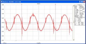
Attached is an image of the filter ripple with the new torroidal core. [The spikes are still present] Pierre's reasoning behind this seems to make sense.
Thanks,
Randy
I replaced the JW miller torroid with a torroidal core I wound with 27.0uH of inductance. When I did my winding I used two strands of #22ga wire in parallel.
I think its from micrometals
approximate dimensions:
Color = RED
OD ~ 1.25
ID ~ 0.75"
Anyway, I ran the amplifier with no input for about 5 minutes without the core heating up. This looked promising so I applied audio [with no load on the output] and I heard this strange "hiss" coming from somewhere on the amplifier board for maybe a second and the fuse on the power supply blew.
This is a first order LC filter with values: L = 27.0uH; C=0.47uF
Theory:
My filter 'Q' is too high causing instability.
Fix:
I do not have a zobel so I either need to add one or increase the coil resistances...
Attached is an image of the filter ripple with the new torroidal core. [The spikes are still present] Pierre's reasoning behind this seems to make sense.
Thanks,
Randy
Attachments
From my experience, you have two different problems:
a) Your circuit blew up probably because you tried to amplify the input signal with no load, and the high Q of the filter probably created a very high voltage. For that, adding a Zobel at the output (22 ohm + 470nF for example, in parallel with the output), will help.
b) The "spikes" (really a ringing at a very high frequency) will cause RFI and interfere with your FM tuner, etc. They are caused, IMHO, by some parasitics that enter resonance at every switching event. I am currently trying to solve this, although I haven't still succeeded.
I have had both problems so it would be very good that we solve them together with the aid of our experts in the forum.
The circuit you have shown is a two stage LC filter , the second one having a "notch", not very useful in a self-osc. design where your switching frequency is variable. And, definitely, not the solution for any of your problems. I recommend to stick to the 2nd order LC by the moment, with the zobel at the end.
Pierre,
I noticed Charles asked if your amplifier was still working. Does this mean another thread exists where I could see your schematic? I agree it would be nice to kill two birds. Meanwhile I will add a 22 ohm + 470nF zobel network to the output and see what happens.
Thanks,
-=Randy
I noticed Charles asked if your amplifier was still working. Does this mean another thread exists where I could see your schematic? I agree it would be nice to kill two birds. Meanwhile I will add a 22 ohm + 470nF zobel network to the output and see what happens.
Thanks,
-=Randy
I added a zobel network to the output of the amplifier
33ohm [2-watt]+ .47uF. Without any audio the amplifier ran stable, however, when I applied an audio signal [100hz, 100mV] I heard a "hissing" sound coming from the audio amplifier. A few seconds later smoke started rolling off the 33-ohm resistor and the fuse on the power supply blew.
Any more ideas?
I would like to note something about the way in which my torroid is wound -- for me to get 27.0uH of inductance I had to wind completely around the torroid 1.5 times. Could the "0.5 times" cause something strange with having too much flux concentrated on one side of the torroid?
Thanks,
-=Randy
I think the output stage is a little untamed as well.
It would be interesting if you could recreate that behavior in spice. Perhaps it’ll be possible to also superimpose the half bridge output with your filter ripple and see what coincides with the spikes in it.
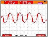
You seem to have at least ten volts overshoot and ringing on the square wave. If it coincides with those, you can measure the ripple frequency and use it to design a snubber to clamp it and dampen the ringing.
Also, don’t forget your choice of mosfet is a controlling factor here, and a major one at that. I believe the next step, as long as you’re sure you have a suitable coil, should be to experiment with different mosfets, before you add anything further. It's worth going through several different types at this stage if you have to in order to optimize it. At these power levels and depending on the quality of PCB it’s also likely that snubbers would improve things anyway.
After all that you’ll be ready to push the oscillation frequency up and see if it all holds, as right now you’re still switching on the low side and if you went higher I think those spikes /RFI/EMI THD etc are bound to be much worse, and you may find it even can’t take it.
As for the coil and the 1.5, I think if you used a proper winding technique it should be alright, like evenly spaced as much as possible or you could look into more advanced methods even.
Also I dont' think or at least understand how a zobel could help with this as it's normally meant to help with a different problem isn't it?
Regards,
Chris
It would be interesting if you could recreate that behavior in spice. Perhaps it’ll be possible to also superimpose the half bridge output with your filter ripple and see what coincides with the spikes in it.
You seem to have at least ten volts overshoot and ringing on the square wave. If it coincides with those, you can measure the ripple frequency and use it to design a snubber to clamp it and dampen the ringing.
Also, don’t forget your choice of mosfet is a controlling factor here, and a major one at that. I believe the next step, as long as you’re sure you have a suitable coil, should be to experiment with different mosfets, before you add anything further. It's worth going through several different types at this stage if you have to in order to optimize it. At these power levels and depending on the quality of PCB it’s also likely that snubbers would improve things anyway.
After all that you’ll be ready to push the oscillation frequency up and see if it all holds, as right now you’re still switching on the low side and if you went higher I think those spikes /RFI/EMI THD etc are bound to be much worse, and you may find it even can’t take it.
As for the coil and the 1.5, I think if you used a proper winding technique it should be alright, like evenly spaced as much as possible or you could look into more advanced methods even.
Also I dont' think or at least understand how a zobel could help with this as it's normally meant to help with a different problem isn't it?
Regards,
Chris
amps?
ihave 2 15 inch 4 ohm subs by pyramid 2400 watts and im getting a concept amp 2400 watt Class-D mono-bloc amplifier will this amp be able to work with the subs fully?
4 Ohm Power (RMS): 600W X 1
2 Ohm Power (RMS): 1150W x 1
1 Ohm Power (RMS): 2400W X 1
Signal-to-noise ratio: 95 dB
Frequency Response: 5 Hz - 350Hz
Total Harmonic Distortion: 0.05%
Input Sensitivity: 200mV-4V
Continuously variable 0 - 18dB Bass Boost
Built-in continuously variable 18dB per octave crossover, from 50Hz to 350Hz
Subsonic filter continuously variable from 15Hz to 40 Hz
Built-in phase switch
Comes with Remote Bass Level Control
Platinum Connectors
Length: 15.5"
Width: 11.66"
Height: 2.37"
Randy, it may not really matter too much about the half fill from the second time around, but increasing the spacing between each second layer turn to bring the winding end back to the beginning could help reduce interference on the circuit. Then the first layer would not have to be redistributed, which would be harder to do due to the increased length and sharper bends in the wire.
Hi All,
I rewound the torroid to 57uH [14GA enameled, tightly wound, symetric winding] and gave it a go but the problem is still present... I talked to Peter, who has made 6 of these, and he did not use a zobel network on the output of his filter...
Does magnetic material itself have such a thing as "Q"? If so perhaps I am using the wrong core material... I noticed Peter's material was dark grey whereas mine is red...
Anyway, with no audio on the input I ran the amplifier for 5 minutes without any problems. When I applied a 100Hz, 100mv signal a "hissing" sound eminated from the amplifier and the fuse on my power supply blew about one second later.
-------------------
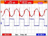
Per Chris's request: Here are some images of the output ripple superimposed with the switching output.
I rewound the torroid to 57uH [14GA enameled, tightly wound, symetric winding] and gave it a go but the problem is still present... I talked to Peter, who has made 6 of these, and he did not use a zobel network on the output of his filter...
Does magnetic material itself have such a thing as "Q"? If so perhaps I am using the wrong core material... I noticed Peter's material was dark grey whereas mine is red...
Anyway, with no audio on the input I ran the amplifier for 5 minutes without any problems. When I applied a 100Hz, 100mv signal a "hissing" sound eminated from the amplifier and the fuse on my power supply blew about one second later.
-------------------
Per Chris's request: Here are some images of the output ripple superimposed with the switching output.
Attachments
- Status
- This old topic is closed. If you want to reopen this topic, contact a moderator using the "Report Post" button.
- Home
- Amplifiers
- Class D
- Help with Class D Amplfier Design (feedback)