Hi all,
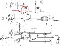
I talked with peter [thread-starter / hypnopete] and he sent me a PCB to play around with. I have everything working properly, however, when I inject a 1-Khz sine wave on the input and increase the amplitude to the threshold of output clipping I destroy Q1 and D2 [MJE340, and 15.6-V zener] every time I try.
At first I just thought this was a "NO-NO" condition for class-D, but when I inject a 1-Khz signal while the amplifier is shutting down the same thing happens. I destroy q1 and d2. This seems like the same problem to me - the voltage rails start tapering off while the input and gain remain constant thus the amplifier clips for a short while destroying q1 and d2.
What causes this, and how can I prevent it?
My theory is that during clipping the control section draws too much current. The problem with this thought is that one would think q1 and d2 would take turns blowing with q3, d3. but ONLY q1, d2 go.[I have done it 6 times with the same results]
Peter's units work fine so what could I be doing wrong?
Thanks!
-=Randy Knutson
Mankato MN
Attachments
Hello Randy,
Sound interesting, I have never had that problem, and I have built 6 of these modules.
What size capacitors are you running for the polarised filtering caps, post MJE340?... Are you using 1Watt Zeners BTW?
Thats what i used on my board, even though I have SMD pads there, I used a 1W axial zener.
Although the power dissipated in the zener is only about 0.042W. thats pretty small.
Have you used an insulating pad between the MJE340 and the heatsink??.
Anyway have to go I'll try and help you out more later.
Regards
Peter
the voltage rails start tapering off while the input and gain remain constant thus the amplifier clips for a short while destroying q1 and d2.
Are you feeding it from a lab-supply or a "real" amp PSU ?
Regards
Charles
Phase Accurate,
This amplifier is powered by a 1kW homebrew switching power supply I made a few months back.
Controller: SG3525
Switching Frequency: 30Khz
12 Volt input
+/-80 Volts output
10,000uF per supply rail.
[The supply is symettric: +82 Volts -83Volts.]
I added a 100uF capacitor across the output of the MJE340 regulator and that didn't help... I also tried increasing the resistor that feeds the zener diode from a 22K to a 39K and that didn't do it either.
The zener diode I am using is in an SMAZ15-13 SMA package rated for 1W.
I pulled the blown transistor from the circuit and measured the
resistances from B-E and B-C and they were both about 0.5 ohms. That
would mean when the MJE340 goes +80V is being shorted directly through ground which explains why I keep blowing fuses.
The only thing I can think of that would cause the MJE340 to go is a
short on the emitter by excessive current consumption of one of the
devices it powers. I'm pretty sure I put everything togerther
correctly because the circuit self-oscillates and amplifies the input
just fine. It only has problems when it is about to clip.
On the other hand the maximum Ic for the MJE340 is 500mA which would
seem like a heck of a lot more than the TL072 + LM319 could take
during any transient. What also worries me is that I have no problems
on the MJE350 regulator section.
The few differences between my implementation and the schematic:
1. I am using TL082 instead of TL072.
2. My smoothing capacitor on the LM319 is 10uF instead of a 47uF.
Ideas?
Thanks!
-=Randy
On the other hand the maximum Ic for the MJE340 is 500mA which would .....
According to the datasheet this drops down to 200 mA @ 80 volts but this would still be enough.
If the load is 10 mA (as an example) then you will end up with .7 Watts approx. This alone will give a temperature rise of more than 70 centigrades.
If your rail is doing funny things one might not know in advance how this is going to behave.
What happens if you connect a resistor in series with the collector in order to distribute dissipation furter ?
What does the rail voltage look like while clipping ? Are there any spikes etc ?
Regards
Charles
Charles,
Thanks for the quick response! On the actual amplifier board I have no bulk capacitance... I was hoping the 10,000uF on the power supply would take care of things, but after further consideration / discussion with Pete I am lead to believe I should add 1000uF directly to each circuit board.
Per your advice Charles I will add a series resistor in series with the collector. 750 Ohms sound good?
Unfortunately I'm all out of MJE340's and SMAZ15 zener diodes so it will be a few days before I can post the results of the modifications.
Thanks!
-=Randy
transistor failure
Randy,
Think about it, there are only a limited number of failure mechanisms that will cause the problem. As Charles pointed out this device has very limited SOA but I would think more than adequate for the job. Of course if it is going into oscillation that would do it. The other thing is voltage stress, like even reverse voltage. Could it be that the TL082 input is protected and diode couples to the power pin if over driven? That could cause the regulator transistor to see way too much Vbe or even reverse Vce voltage on shut down.
My guess is oscillation though. Been there, done that!
Roger
Freq.
Randy,
Way too many variables to be sure but I would guess 1-10MHz range. A .1uf on each collector to close ground points would kill this possibility and be easier to try than poking around with a scope, trying to catch the event just before it blows. However a scope on the opamp power pin and carefully increasing the input signal could impart some very useful info.
Roger
Hi Randy,
I think the fact that there are no storage capacitors on the board, will cause major issues. I have never ever had this problem and I have assembeled many of these boards. Without the capacitors there you have to take into account all the stray inductance of all the power leads running to the amp, as well as there resistance. I designed that board such that there was minimal track distance between the two storage capacitors and the half bridge, as well as very thick, solder masked tracks.
See how you go with those capacitors there, after all they do provide the supply for the voltage regulators as well.
Regards
Peter Reid
I think the fact that there are no storage capacitors on the board, will cause major issues.
That's my feeling as well !!!
Regards
Charles
Yes, they started working quite well as soon as I replaced onsemi's mosfets with IRF ones.
Now that you ask, I noticed that the amp oscillated a little at high power levels as soon as I increased the supply rails to +/-65V. (all the development was done with +/-45V) I suppose that this is caused by the increased loop gain that reduces phase margin. I have almost solved it by increasing the feedback resistor, hence reducing feedback, so an increase in THD may be logical.
BTW: my amp mounts 220uF in parallel with 0.1uF ceramics per rail.
I have been on holidays so I haven't have time to sort all the info, schematics, etc in order to share them. I am with it, I promise!
Best regards.
Hey All,
Thanks for the replies!! I don't know what I would do without this forum!") Anyway, I made my parts list, but I read the new posts this morning and if hypex uses 470uF per rail and LCaudio uses 150uF would I be going overboard using 1800uF per rail? [the board will allow it]
Anyway, I made my parts list, but I read the new posts this morning and if hypex uses 470uF per rail and LCaudio uses 150uF would I be going overboard using 1800uF per rail? [the board will allow it]
Here are the capacitor details:
C = 1800uF
ECO-S2AP182BA
diameter = 22mm
Max 85degC R.C. [Arms]
120Hz = 2.52
10Khz = 2.90
Max 20degC ESR [ohms]
120Hz = 0.147
20Khz = 0.111
What is R.C.?
As soon as I get the diy seal of approval that this capacitor will work I will order the new parts.
Thanks!
-=Randy Knutson
Thanks for the replies!! I don't know what I would do without this forum!
Anyway, I made my parts list, but I read the new posts this morning and if hypex uses 470uF per rail and LCaudio uses 150uF would I be going overboard using 1800uF per rail? [the board will allow it] Here are the capacitor details:
C = 1800uF
ECO-S2AP182BA
diameter = 22mm
Max 85degC R.C. [Arms]
120Hz = 2.52
10Khz = 2.90
Max 20degC ESR [ohms]
120Hz = 0.147
20Khz = 0.111
What is R.C.?
As soon as I get the diy seal of approval that this capacitor will work I will order the new parts.
Thanks!
-=Randy Knutson
Randy Knutson said:
What is R.C.?
Ripple Current.
Bigger cap is not necessarily better than smaller, you can run to problems with series inductance. Your cap specifications didnt say anything about it and also it was specified for esr at 20khz. you may wish from your heart that esr is not rising above 100khz.
our beloved ESR of electrolytics in smps , too much of it and it will explode and too low esr and control loop
goes insane. Sometimes lousy high-esr cap is all you need to stabilise high-Q oscillation at decoupling caps(snubberized in this forum)
Anyways, give it a try

mzzj said:
Sometimes lousy high-esr cap is all you need to stabilise high-Q oscillation at decoupling caps
Yeah, 470u/100v Yageo from the UcD400, have around 52mOhm ESR, and around 15nHn ESL, i not remember who exactly advised to take Elna Cerafine 470u/63v (probably BP), however this cap is pretty low ESR (17mOhm and the same ESL as Yageo).. well, Yageo replaced anyway, and sound little better (at the imagination level, i guess;-) not worst at least, THD, IMD, Noise Floor - exactly the same, hence ESR=17mOhm isn't low too much. Maybe differences so insignificant, because power tank cap, in the setup, have around 4mOhm ESR (Epcos B41554-E8229-Q), with thick-short wires, or i'm just not so much advanced listener.
Hey All!
@ Peter and PhaseAccurate.
Your hunches were correct! As soon as the capacitors arrived I threw them on the PCB and NO MORE PROBLEMS!! -- Thanks for helping me out !
Unfortunately, I'm in the process of moving and my dummy load is in a storage shed so it will be 3-4 days before I can analyze the amplifiers performance into a load, however, I attached some no load pics and everything looks good [to me atleast].
Thanks again!
Randy
The 1st image is the output before the filter:
Attachments
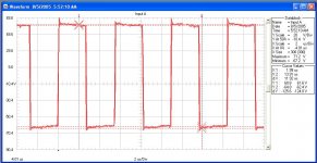
I measured the switching frequency to be 183.0 Khz. Is it wise to try and increase my switching frequency to 220 or so KHz?
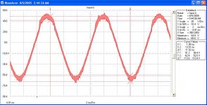
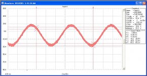
The image in this post is of the amplified output right before clipping. I notice near the crests the frequency drops. I have seen talk of this on the forum, but what exactly causes this?
The image in this post is of the amplified output right before clipping. I notice near the crests the frequency drops. I have seen talk of this on the forum, but what exactly causes this?
Attachments
- Status
- This old topic is closed. If you want to reopen this topic, contact a moderator using the "Report Post" button.
- Home
- Amplifiers
- Class D
- Help with Class D Amplfier Design (feedback)