Here is what I personally think:
- Get rid of the input transformer, you dont need it. Ground one input, or use it for feedback. (Or better, build a balanced pre)
- I'd use more voltage for the pre-amplifier. Also, the resistor values of this stage doesnt seem right to me, minimum current through 2 tubes is 6.25 mA (1.25V / 200 ohm)
To get the voltages right, 250V +++ and 200V on anodes, you would need less then 2mA per tube.
B+++ 350V and about 7mA per tube seems better to me
- I would prefer to use fixed bias for the 807's instead of that LM317 circuit. (I dont like those big caps at the cathodes of the 807.) But that is just personal offcourse.
PS: I do like all other things about it!
hidnplayr,
- Get rid of the input transformer, you dont need it. Ground one input.
I'll try to learn more about this.
- I'd use more voltage for the pre-amplifier. Also, the resistor values of this stage doesnt seem right to me, minimum current through 2 tubes is 6.25 mA (1.25V / 200 ohm)
To get the voltages right, 250V +++ and 200V on anodes, you would need less then 2mA per tube.
B+++ 350V and about 7mA per tube seems better to me
I thought the 200 ohm is the multi-turn pot, so I could adjust the current easily, or I miss something here.
- I would prefer to use fixed bias for the 807's instead of that LM317 circuit. (I dont like those big caps at the cathodes of the 807.) But that is just personal offcourse.
Fixed bias is good, but you don't know if the tubes are working in balance, or I don't have to worry about that
Albert
I thought the 200 ohm is the multi-turn pot, so I could adjust the current easily, or I miss something here.
You used a 200 ohm resistor, when the resistor has it's maximum value (200 ohm) the current thrugh the lm317 will be 1.25V / 200 ohm = 6.25 mA
You can only increase that current by turning your pot.
I think the current, 6,25 mA minimum is good, but at this current, the voltages do not work out! you need to change the values of anode resistors, or the B+++, or both.
If you use fixed bias, you generall place a small resistor (1 ohm or 10 ohm being very common) in the cathodes of the output tubes.Fixed bias is good, but you don't know if the tubes are working in balance, or I don't have to worry about that
By measuring the voltage over this resistor, you can then know the current through the tube.
The BIAS circuit should have 2 potmeters per channel, a BIAS and a balance.
You can then adjust the balance potmeter so you have the exact same voltage over both cathode resistors
If it's a good input transformer, it brings a lot of advantages with it. First, galvanic isolation. Second, common mode rejection. Third, the ability to use balanced or unbalanced sources. Fourth, presentation of a balanced signal to the following stages (no phase splitter imbalance errors).
I'd probably use a better CCS in the cathodes of the input stage than a 317. Cascoded MOSFETs or even a simple bipolar are not much more complex, cost very little, and have far better performance, especially at high frequencies.
edit: I just noticed that the CCS are also under the output stage. Upon overload, recovery time will be quite long. That's not what you want.
SY,
Thanks for your suggestion.
I'd probably use a better CCS in the cathodes of the input stage than a 317. Cascoded MOSFETs or even a simple bipolar are not much more complex, cost very little, and have far better performance, especially at high frequencies.
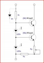
How about a cascode DN2540 for the position, or something like the attached
edit: I just noticed that the CCS are also under the output stage. Upon overload, recovery time will be quite long. That's not what you want.[/QUOTE]
So you prefer the traditional auto bias/ fixed bias
BR
Albert
Thanks for your suggestion.
I'd probably use a better CCS in the cathodes of the input stage than a 317. Cascoded MOSFETs or even a simple bipolar are not much more complex, cost very little, and have far better performance, especially at high frequencies.
How about a cascode DN2540 for the position, or something like the attached
edit: I just noticed that the CCS are also under the output stage. Upon overload, recovery time will be quite long. That's not what you want.[/QUOTE]
So you prefer the traditional auto bias/ fixed bias
BR
Albert
Attachments
Your schematic looks like a variation on Shoog's 807 amp.
Search this forum. He seemed to like it.
There is where I copied from. Steve is good to answer all my questions and actually I finished couple amps with his design and that sound very good. I therefore try to make something with all the parts that I have on the bin
Albert
SY,
How about a cascode DN2540 for the position, or something like the attached
Both those solutions are easy and way outperform anything you'll need. Blameless, as it were.
So you prefer the traditional auto bias/ fixed bias
I think overload recovery is very important. Some traditional schemes do very well at that, some don't. But it's easy to design for and pays off in sound quality when the music gets busy. With CCS, it's a lot more difficult.
I think overload recovery is very important. Some traditional schemes do very well at that, some don't.
SY,
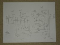
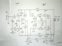
I scratch another one which I thought would be quite close to those traditional schemes. Please take a look and do give comment on anything I can do better.
Thanks
Albert
SY,
I scratch another one which I thought would be quite close to those traditional schemes. Please take a look and do give comment on anything I can do better.
Thanks
Albert
Attachments
You'll probably want C1 and C2 to return to the cathodes rather than ground. 0u1 and 1M will give good balance into the subsonic region. But make sure that the RC coupling to the output stage has a time constant that's at least 5 times shorter in order to get good bass stability.
Time constant is the product of R and C. For 0u1 and 1M, it's 0.1 second. So you'd want the RC time constant of the RC coupling of the next stage to be 0.02 second or smaller (corresponds to an 8 Hz -3dB point before feedback). If you can get your hands on Norman Crowhurst's "Understanding HiFi Circuits," there are excellent charts to show how far time constants need to be staggered for stability for different numbers of rolloffs within a feedback loop.
Time constant is the product of R and C. For 0u1 and 1M, it's 0.1 second. So you'd want the RC time constant of the RC coupling of the next stage to be 0.02 second or smaller (corresponds to an 8 Hz -3dB point before feedback). If you can get your hands on Norman Crowhurst's "Understanding HiFi Circuits," there are excellent charts to show how far time constants need to be staggered for stability for different numbers of rolloffs within a feedback loop.
Thanks,
I'll look up for that
Can you explain your choice of the ECC86 as a preamp stage?
I think you better save this low-voltage valve for other projects.
(Headphone amplifier anyone?)
I read an article talking about the correction of phase, so I thought I need this stage for the phase purpose. If not, I save this for the other project. I have a preamp to hook up to.
I read an article talking about the correction of phase, so I thought I need this stage for the phase purpose. If not, I save this for the other project. I have a preamp to hook up to.
So you added another gain stage because you wanted 180° of phase rotation?
That is not nescessary, if you are concerned about absolute phase, you can change it at other places:
- The long tailed pair has 2 input, if you switch them, you rotate the input 180°
- Same thing can be done at the output transformer, by switching the anode leads.
PS: have you calculated the gain of your 6au6 stage? how much volts on the input do you need to fully drive the 807's ?
(The datasheet will probably say how much volts you need on the grids of 807)
According to the datasheet, Peak AF Grid Voltage
Class A 60v
Class AB1 40v
- Status
- This old topic is closed. If you want to reopen this topic, contact a moderator using the "Report Post" button.
- Home
- Amplifiers
- Tubes / Valves
- Help to find out what OPT are these