Capacitor change list
Here is my planned cap change list:
Electrolitics
OsCon
C301 - 47/50 =>47/20
C302 - 220/50(470/6.3) =>220/10
C303 – 100/25 =>100/20
C341 - 100/50(10) =>100/20
C351 - 220(330)/25 =>220/10
C407 - 100/50 =>100/20
C322 – 220/25 =>220/10
C160,162 - 4.7/50 =>4,7/25
C422 - 4.7/50 =>4,7/25
BlackGate
C405 – 470/50(6.3) =>1000/16 std.
C27 -220/25 =>1000/16 std.
C433,434 - 100/50 =>100/6.3 NX
Panasonic FC
C52 – 100/50 =>330/50
C211,212 - 220/25 =>330/25
C216,217 - 220/25 =>330/25
C431,432 - 220/25 =>330/25
C151 - 220/25 =>330/25
C153 - 100/10 =>330/25
Vishay BC
C25,26 – 3300/16 =>4700/16
Polypropylen, Polyester(originaly ceramics)
IC151
C167 - 0,01 =>10nF
C168 - 0,033 =>33nF
C169 - 0,01 =>10nF
C170 - 0,0033 =>3,3nF
C171 - 0,001 =>1nF
C172 - 0,0047 =>4,7nF
C155 - 560P =>0,56nF
C156 - 0,033 =>33nF
C157 - 0,01 =>10nF
C159 - 0,1 =>100nF
C163 - 0,1 =>100nF
PSU
C11 - 0,047 =>47nF
C19 - 0,01 =>10nF
C15,16 - 0,047 =>47nF
all the rest
C406 - 270P =>0,27nF
C461 - 0,01 =>10nF
C306 - 0,0015 =>1,5nF
C307 - 0,047 =>47nF
C308 - 0,01 =>10nF
C309 - 0,47/50(was electrolit.)=>470nF
C342 - 0,01(0,15) =>10nF(150nF)
C205 - 0,01 =>10nF
C210 - 0,01 =>10nF
C215 - 0,01 =>10nF
C218 - 0,027 =>27nF(33nF)
C219 - 0,01 =>10nF
C352 - 0,01 =>10nF
C353 - 0,01 =>10nF
C354 - 0,047 =>47nF
SILVERED MICA(originaly ceramics)
C429,430 - 39pF =>39PF
C435,436,437,438 - 4,7pF =>4,7PF
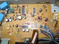
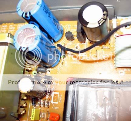
I have currently changed all the ceramics on board, except the ones that are to be changed with micas. I relay did not expect some great improvement, but it turned as audible as much as the OpAmp change! I'm still waiting for diodes, elcos, clock parts... Here is the pic:
Here is my planned cap change list:
Electrolitics
OsCon
C301 - 47/50 =>47/20
C302 - 220/50(470/6.3) =>220/10
C303 – 100/25 =>100/20
C341 - 100/50(10) =>100/20
C351 - 220(330)/25 =>220/10
C407 - 100/50 =>100/20
C322 – 220/25 =>220/10
C160,162 - 4.7/50 =>4,7/25
C422 - 4.7/50 =>4,7/25
BlackGate
C405 – 470/50(6.3) =>1000/16 std.
C27 -220/25 =>1000/16 std.
C433,434 - 100/50 =>100/6.3 NX
Panasonic FC
C52 – 100/50 =>330/50
C211,212 - 220/25 =>330/25
C216,217 - 220/25 =>330/25
C431,432 - 220/25 =>330/25
C151 - 220/25 =>330/25
C153 - 100/10 =>330/25
Vishay BC
C25,26 – 3300/16 =>4700/16
Polypropylen, Polyester(originaly ceramics)
IC151
C167 - 0,01 =>10nF
C168 - 0,033 =>33nF
C169 - 0,01 =>10nF
C170 - 0,0033 =>3,3nF
C171 - 0,001 =>1nF
C172 - 0,0047 =>4,7nF
C155 - 560P =>0,56nF
C156 - 0,033 =>33nF
C157 - 0,01 =>10nF
C159 - 0,1 =>100nF
C163 - 0,1 =>100nF
PSU
C11 - 0,047 =>47nF
C19 - 0,01 =>10nF
C15,16 - 0,047 =>47nF
all the rest
C406 - 270P =>0,27nF
C461 - 0,01 =>10nF
C306 - 0,0015 =>1,5nF
C307 - 0,047 =>47nF
C308 - 0,01 =>10nF
C309 - 0,47/50(was electrolit.)=>470nF
C342 - 0,01(0,15) =>10nF(150nF)
C205 - 0,01 =>10nF
C210 - 0,01 =>10nF
C215 - 0,01 =>10nF
C218 - 0,027 =>27nF(33nF)
C219 - 0,01 =>10nF
C352 - 0,01 =>10nF
C353 - 0,01 =>10nF
C354 - 0,047 =>47nF
SILVERED MICA(originaly ceramics)
C429,430 - 39pF =>39PF
C435,436,437,438 - 4,7pF =>4,7PF
I have currently changed all the ceramics on board, except the ones that are to be changed with micas. I relay did not expect some great improvement, but it turned as audible as much as the OpAmp change! I'm still waiting for diodes, elcos, clock parts... Here is the pic:
Attachments
Hi Bassivus,
thanks for your advice on the modifications. And thanks to all the others too.
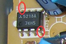
Today I did a first step with mine: Changed the opamp of the LP. It is now a ne5532 - the only thing I had at hand right now. I pulled out the muting transistors.
Even though the ne5532 is not the last word in opamps, the sound improved a lot.
After a first test, I soldered out the op of the headamp, I don't need it right now. This helped the soundstage a little.
Best regards
Floric
thanks for your advice on the modifications. And thanks to all the others too.
Today I did a first step with mine: Changed the opamp of the LP. It is now a ne5532 - the only thing I had at hand right now. I pulled out the muting transistors.
Even though the ne5532 is not the last word in opamps, the sound improved a lot.
After a first test, I soldered out the op of the headamp, I don't need it right now. This helped the soundstage a little.
Best regards
Floric
Hello Floric,
Glad that you enjoyed the thread and decided to your player.
I did not change the C441/442 because I remember reading somewhere they are quite OK, but you have definately missed the C433/434. In the post :
http://www.diyaudio.com/forums/showthread.php?postid=1009382#post1009382
I refer to those. They give great transparency, detail and soundstage - BUT I find them waaay to bright! Recently I have changed them with BlackGate NX ... (as in the cap change list)
I will post my recent mod pics and impressions soon...
All the best, Ivica
Glad that you enjoyed the thread and decided to
your player.Floric said:Sorry if I missed it in the thread.
Didn't you change C441/C442 and C433/C434?
If you did (and I missed it) what did you choose instead. If not why? They seem to be very important for the LP section.
Best regards
I did not change the C441/442 because I remember reading somewhere they are quite OK, but you have definately missed the C433/434. In the post :
http://www.diyaudio.com/forums/showthread.php?postid=1009382#post1009382
I refer to those. They give great transparency, detail and soundstage - BUT I find them waaay to bright! Recently I have changed them with BlackGate NX
... (as in the cap change list)I will post my recent mod pics and impressions soon...
All the best, Ivica
Help, I fried my one
Today I fried my PD s505. I changed the opamp to opa2134 - sounded good. Then I gave it a try and decoupled V+ to V- with a 100n MKT cap. When I powered it on (plugged in the mains), the drive made strange noises and there was no light on the LEDs and the display. I removed the plug immediately then I removed the opamp with the decoupling across the pins and inserted the ne5532 (without decoupling) again. After plugging in nothing happened - no lights no spinning of the drive.
Measuring V+ to V- gave about 10V. Mesuring V+ to V- on the (empty) socket for the opamp for the headphone gave about 20V which is o.k. I think.
Studying the schematics gave two possible eplanations: I fried the decoupling caps C431/C432 (this possibility is very low I think) with that action or the IC Protector IC31 went "over the jordan". Is this possible? As far as I understand the datasheet of this ICP-N10, even a too high current would not matter (this is what the device is for).
So please answer my question: What happened and how to repair it?
Thank you very much in advance.
(sad) Floric
Hi zanash
thanks for your reply.
The decoupling that way is already implemented on the board. In addition to that it is almost common to use a relatively small cap from Ve+ to Ve-. This is often referenced (e.g. here and in Mauro Penasas Rev C Amp or in several Application Notes) I did it already in other projects. Especially with the OPA2132/2134 this gives a noticealbe improvement of the sound.
But what could be damaged by this additional capacity?
Best regards
Floric
thanks for your reply.
The decoupling should be from +ve rail to ground not -ve and visa versa ....well thats how I've always done it .......
The decoupling that way is already implemented on the board. In addition to that it is almost common to use a relatively small cap from Ve+ to Ve-. This is often referenced (e.g. here and in Mauro Penasas Rev C Amp or in several Application Notes) I did it already in other projects. Especially with the OPA2132/2134 this gives a noticealbe improvement of the sound.
But what could be damaged by this additional capacity?
Best regards
Floric
Hi, I don't have the thing here at the moment, I will measure later.
But it would be possible, that I missinterpreted the word "repeatable" in the datasheet of the ICP-N10. I thought, that the thing is a kind of switching fuse, that switches if the current exeeds 0,4A. But now I think it is a fuse that gets demolated by a current bigger than 0,4A and "repeatable" means a kind of series constancy.
Then it could be possible, that the additional capacity I added caused some oscillations which caused a too high current...
That would explain why nothing works any more.
I will measure later on.
Thanks
Floric
Now I had time to measure. The ICP-N10 (IC31) had a resistance of 35MOhm, it is a fuse and the current was too high for a moment. When that device is broken, you get really strange voltages all over the board.
I replaced IC31 with a piece of wire for the tests - I am going to order ICP-N10 these days - and everything worked fine without the decoupling cap on he opamp.
What I learned: A cap from Ve+ to Ve- can cause a too high current. I am still wondering why, I think the ps is b.s. and that "repeatable" in a worksheet means that what we call "reproduzierbar" in German - I would translate it as "reproducible" and not "wiederholbar".
Sleep well and thans again
Floric
I´ve had those caps on another construction,and it worket fine,those from + to ground and - to ground should have better effect thoug.A cap from Ve+ to Ve- can cause a too high current
It sounds like the classic short curcuit ....... but glad you've found it.
There are better mods !
I'm assuming you've done the diodes
the output caps
signal path resistors
better sockets hard wire with at least silver
point to point silver wireing of the pcb output stage
bypass all electrolytic caps
case damping
case stiffening
fitting an iec main socket
the list goes on .....
I´ve had those caps on another construction,and it worket fine,those from + to ground and - to ground should have better effect thoug.
Me too, but in that configuration it did not work.
It sounds like the classic short curcuit ....... but glad you've found it.
Me too
! But I would be interested in the Reason - to learn something. In this step the only thing I did was the addition of the cap. I controlled the rails of the cat there was no short circuit. The only theory I have is that there are oscillations caused by the ps. Have to look for an oszi to prove that.There are better mods !
Yes I know and I will do some of them. At first I wanted to improve the opamp of the output. Until now I have "done" loudspeakers, amps and Turntables this is my first digital audio mod and I want to go step by step and test the changes.
Until now it is amazing because the change of the opamp and the removement of the muting circuit improved the thing a lot - I did not like it before.
Thanks for your answers
With best regards
Floric

Hello,
Floric I'm glad to hear that you didn't burn nothing else than ICP-N10...
Two weeks ago I was measuring around newly fitted diodes in PSU section when the tip of my meter accidentally slipped and shortciruted it
...zzzaaap.... ...
... ooo its frying time again ....
The result was the same as yours - ICP-N10 dead ... I found them with NEDIS to save you time for searching.
Best regards
Ivica
Floric I'm glad to hear that you didn't burn nothing else than ICP-N10...
Two weeks ago I was measuring around newly fitted diodes in PSU section when the tip of my meter accidentally slipped and shortciruted it
...zzzaaap....
... ooo its frying time again ....The result was the same as yours - ICP-N10 dead
... I found them with NEDIS to save you time for searching.Best regards
Ivica
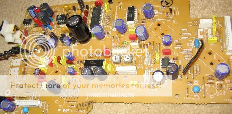
Silicon in every hole:
Oh, you have been really hard working! How does it sound?
The result was the same as yours - ICP-N10 dead ...
The strange thing are the really strange voltages you measure all over the board with a dead ICP-N10.
I found them with NEDIS to save you time for searching.
Thanks but I already decided not to follow the service manual and use only ICP-N10. I ordered N10 via Reichelt, don't know the manufacturer right now.
Nice pic ...you've put a considerable amount of work in on that cdp.....
I was doing someone elses machine and working to a budget so never got that far.....
I had a persistant skip ....this caused no end of problems as i could not locate the cause.
In the end I cleaned all the cogs by pressing blutac into each tooth ...what ever had been fouling the mech was removed. 3yrs on its still playing ....
Well,it sounded sa good as,or better than my DV668,wich I now have sold..Oh, you have been really hard working! How does it sound?
Hi everybody,
Here is the short report on the current status of my moding effort.
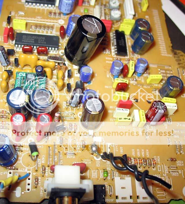
I have changed the diodes with 11DQ10 (thanks Zanash!), installed all the caps (finally) as listed in my cap change list, and I am currently busy finishing and implementing the Kwak-Clock. In one of the pics you can see I have also filled some gaps but not so tidily as Ryssen.
I am so pleased with the sound improvement (even without the clock yet) that I think I’m going to change the course of my initial plan of making it mostly a good transport for external DAC. I’m seriously considering of introducing the extra supply with the super regulator for the analog out, as the further improvement.
Regards
Ivica
Here is the short report on the current status of my moding effort.
I have changed the diodes with 11DQ10 (thanks Zanash!), installed all the caps (finally) as listed in my cap change list, and I am currently busy finishing and implementing the Kwak-Clock. In one of the pics you can see I have also filled some gaps but not so tidily as Ryssen.
I am so pleased with the sound improvement (even without the clock yet) that I think I’m going to change the course of my initial plan of making it mostly a good transport for external DAC. I’m seriously considering of introducing the extra supply with the super regulator for the analog out, as the further improvement.
Regards
Ivica
- Status
- This old topic is closed. If you want to reopen this topic, contact a moderator using the "Report Post" button.
- Home
- Source & Line
- Digital Source
- Help me mod Pioneer PD-S505/605