zanash said:snubbers are small value film caps placed across the diodes to dampen the noise created when the rectifier switch back and forth
Thanks!!! You know my first lenguage is not English and my job is not electonics
 ...every day to learn someting new
")
RETURN OF THE TRANSFORMER QUESTION
Please bare with me.
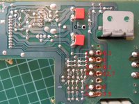
I have put this question on the beginning of the thread but the debate went in other direction and left it unanswered. We covered the rectification, diodes, caps part, mostly. I did not get an clear opinion about what to do with the trafos. I have read that putting the bigger trafo can help a lot. Since my CDP has really small trafo feeding everything, I have done some thinking and came to conclusion that it might be good idea to cut off leads of existing trafo-marked 1,2,3 - leave in in place to feed the rest. In the place of removed introduce power from the new separate toroid transformer.
- the questions are:
1. Should I even bother with this - is it worth the money/time?
2. If yes - Do I read the measurements right- I need 8 V secondary(or should it be 9V?).
3. How big the new trafo should be?
I have done some measurement with the CDP in stand by mode as you can see in the attachment:
Please bare with me.
I have put this question on the beginning of the thread but the debate went in other direction and left it unanswered. We covered the rectification, diodes, caps part, mostly. I did not get an clear opinion about what to do with the trafos. I have read that putting the bigger trafo can help a lot. Since my CDP has really small trafo feeding everything, I have done some thinking and came to conclusion that it might be good idea to cut off leads of existing trafo-marked 1,2,3 - leave in in place to feed the rest. In the place of removed introduce power from the new separate toroid transformer.
- the questions are:
1. Should I even bother with this - is it worth the money/time?
2. If yes - Do I read the measurements right- I need 8 V secondary(or should it be 9V?).
3. How big the new trafo should be?
I have done some measurement with the CDP in stand by mode as you can see in the attachment:
Attachments
Ceramic caps
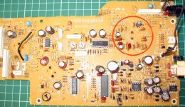
Maybe the silly question but I have noticed that in my player there are quite a bit ceramic caps specially around servo and when I look at more expensive players there are much less ceramic an more polipro. I have read somewhere that ceramics are no good for audio circuit. I mean I know that its no good to use them in audio path, but I wonder if it is of any good to replace some of them with something better?
Maybe the silly question but I have noticed that in my player there are quite a bit ceramic caps specially around servo and when I look at more expensive players there are much less ceramic an more polipro. I have read somewhere that ceramics are no good for audio circuit. I mean I know that its no good to use them in audio path, but I wonder if it is of any good to replace some of them with something better?
Attachments
Look for film caps of the same value ....in certain places these will make a difference. If you can also bypass lagre electrolytic cap with film caps this will also give a significant benifits.
the rule is that a cap with a value of 10000uf should be bypassed with 100uf 10 uf 1uf [the last can be a film cap]. The reason behind this is to do with reaction times of the larger caps..if you get a transient you will want the psu to respond very quickly to it smaller caps are better at this, but don't hold much power. The small caps react first and help maintain the leading edges that are so important in the reproduction of the music signal.
the rule is that a cap with a value of 10000uf should be bypassed with 100uf 10 uf 1uf [the last can be a film cap]. The reason behind this is to do with reaction times of the larger caps..if you get a transient you will want the psu to respond very quickly to it smaller caps are better at this, but don't hold much power. The small caps react first and help maintain the leading edges that are so important in the reproduction of the music signal.
Bassivus said:Help me mod Pioneer PD-S505/605
I am planning to upgrade my player to decent standalone player but I bought it primarily for transport/DAC use(I don't own no DAC yet!) I have no education in electrics, but I have some previous experience, tweaking my Philips 721 CDP and building WNA headamp.
My basic strategy is:
1. Upgrade power section with pretty toroid, Caps....
2. Clock it with KwakClock
3. For analog section swap the NJM4558 with some AD826 ...
--------------------
I found the free scheme for download:
http://www.eserviceinfo.com/downloadsm/22612/Pioneer_pd-s605.html
(scroll the page down a bit for the Download link)
Some years ago i demounted my Pioneer PD-S504 into small pieces..
I still havent put it together again
 and I probably wouldnt be able to, because forgot how it was
Reason was maily to upgrade to a better output amplifier.
NJM4558 is not very impressive Op-Amp, compared to what we have today.
And of course, upgrade the output electrolytic capacitor, or even remove it, if possible.
While I was at it, I decided to remove the Mute transistor circuitry at output.
To do this, I backengineered all the CD-player PCB and draw the full schematic onto paper.
Took me several weeks!
I still have those papers somewhere in a wardrobe
along with that Pioneer CD-player PD-S504 and all them screws and loose demounted components.
This project is dead, I have a new and better up-to-date CD-Player
but sure is
I learnt a few useful things while doing it.
And this Pioneer machine is basically very good. Still.
PD-S505 is even a snap better in quality.
Good Luck, Bassivus
lineup said:
Some years ago i demounted my Pioneer PD-S504 into small pieces..
I still havent put it together again
Thats why I take MANY pictures!
To do this, I backengineered all the CD-player PCB and draw the full schematic onto paper.
Took me several weeks!
Ha! If you had my knowledge you would be near finishing it about now and we could share experiences
Good Luck, Bassivus
THANKS!!!
in my attached image
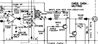
- you can see the 1/2 4558 OP amplifier
- output cap C434, in my player was 100uF/50V elyt
- and all the muting junk they have added, before the Line Out RCA jacks
by the way, in my PD-S504
the headphone amplifier, if we do even want to call it this
was a small dual..!! older model op-amp, with gain=1 ( buffer )

think it is the same as can be seen in that service manual for PD-S505
Bassivius,
thanks very much for the download
maybe can make me finished this CD-mod project
lineup better late, than never - to finish your projects and ideas
- you can see the 1/2 4558 OP amplifier
- output cap C434, in my player was 100uF/50V elyt
- and all the muting junk they have added, before the Line Out RCA jacks
by the way, in my PD-S504
the headphone amplifier, if we do even want to call it this
was a small dual..!! older model op-amp, with gain=1 ( buffer )
think it is the same as can be seen in that service manual for PD-S505
Bassivius,
thanks very much for the download
maybe can make me finished this CD-mod project
lineup
better late, than never - to finish your projects and ideasAttachments
Report
I first swapped NJM4558 with AD826 - much better. It was hard to tell how much improvement was to OpAmp alone because I did it at the same time I cut out the muting. Then I have tried AD825 on Audiocom adapter (I have from before), for some days now and compared it to AD826. Despite I thought it should be just single version of AD826 it somehow menages to beat it. Initially I thought it was because it was new and not properly broken in but the audible margin is still there.
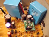
Today I was busy as you can see in the attachment. I have done some big caps bypassing and CHANGED OUTPUT CAPS. I had a pair of EVOX-RIFA 4.7uF caps hanging around and thought to give them a try. I had no chance to listen to it yet. I have forget to measure the offset before the change but now it measures 0,5mV. Is it OK?!?!
I first swapped NJM4558 with AD826 - much better. It was hard to tell how much improvement was to OpAmp alone because I did it at the same time I cut out the muting. Then I have tried AD825 on Audiocom adapter (I have from before), for some days now and compared it to AD826. Despite I thought it should be just single version of AD826 it somehow menages to beat it. Initially I thought it was because it was new and not properly broken in but the audible margin is still there.
Today I was busy
as you can see in the attachment. I have done some big caps bypassing and CHANGED OUTPUT CAPS. I had a pair of EVOX-RIFA 4.7uF caps hanging around and thought to give them a try. I had no chance to listen to it yet. I have forget to measure the offset before the change but now it measures 0,5mV. Is it OK?!?!Attachments
whose mistake is it?
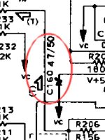
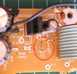
Today I have come to strange finding.
I looked to schematics serching for possible good place to use spare 47uF Oscons. I found 3 places with 47uF in the schematics. I searched for them on the board itself and found that they are not 47 but 4.7!!!
Now I'm wondering is it the bad scan of scheme to blame for non visible dot or it actualy is 47uF supposed to be in those positions but by some fault they mounted 4.7?
Attachments
WARNING!!!
I want to warn everybody who intends to use schematics that I gave link to in the beginning of this thread. Because of the bad quality of scan some details are lost. There are more more mistakes like the one I have shown in my last post! Many dots and commas are missing.
I want to warn everybody who intends to use schematics that I gave link to in the beginning of this thread. Because of the bad quality of scan some details are lost. There are more more mistakes like the one I have shown in my last post! Many dots and commas are missing.

- Status
- This old topic is closed. If you want to reopen this topic, contact a moderator using the "Report Post" button.
- Home
- Source & Line
- Digital Source
- Help me mod Pioneer PD-S505/605