"I have not found data that confirms shape to parasitics."
http://www.diyaudio.com/forums/mult...igning-crossovers-without-measurement-48.html
Post #478 ...
Floating in this sea of green... Never believing anything I see...
http://www.diyaudio.com/forums/mult...igning-crossovers-without-measurement-48.html
Post #478 ...
Floating in this sea of green... Never believing anything I see...
Last edited:
Some published data is to simplify math. 1000, 100, 10 etc. But I'd like to back myself up and contribute by making bunch of ferriteless (that'do) coils to back up claim. Dropping a zero or two makes sense.
Winding ones own should be accepted and butted, as coils of wire are less understood as are energy storing medium, such as capacitors. Both should mysterious! and treated the same. stick your tongue on battery or coil, same experiment. Ya learn !!!
Winding ones own should be accepted and butted, as coils of wire are less understood as are energy storing medium, such as capacitors. Both should mysterious! and treated the same. stick your tongue on battery or coil, same experiment. Ya learn !!!
Hey John. Good work there! What material is the bolt made from? Obviously iron (in steel) would affect inductance of the coil... I wonder what s/s (stainless steel) would work like ?
Going air cored increases size of coil but removes any chance of core-saturation. The valve (tube) guy's like me enjoy the sound, but the o/p trannie is normally iron!!!
My original plan was to use wood. Dowel and ply wood to be exact. Then glue together using PVA or similar. Much cheaper than perspex! We recycled perspex from a friend's race car window!!
I proposed using square sides for vertically mounted inductors, as this means mounting to PCB would be easier... not so much of an issue with flat mounting.
Also, do you guy's remove dowel and sides and either glue or cable tie inductors together?? ie minus the former...
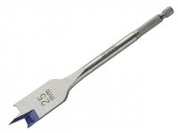
We used bit like this in drill press to cut out 20mm hole into perspex sheet before we cut out each square with hacksaw...
Going air cored increases size of coil but removes any chance of core-saturation. The valve (tube) guy's like me enjoy the sound, but the o/p trannie is normally iron!!!
My original plan was to use wood. Dowel and ply wood to be exact. Then glue together using PVA or similar. Much cheaper than perspex! We recycled perspex from a friend's race car window!!
I proposed using square sides for vertically mounted inductors, as this means mounting to PCB would be easier... not so much of an issue with flat mounting.
Also, do you guy's remove dowel and sides and either glue or cable tie inductors together?? ie minus the former...
We used bit like this in drill press to cut out 20mm hole into perspex sheet before we cut out each square with hacksaw...
Attachments
Last edited:
Yeah the bolt was annoying, as it was removed it for each measurement.
It's easier to leave the former / bobbin in place. Wolf made a nifty jig from plexi.
Typically I'm making a inductor because it's a weird size or prototype while I wait for something to arrive. I still use the plastic ebay bobbins for tweeter inductors.
It's easier to leave the former / bobbin in place. Wolf made a nifty jig from plexi.
Typically I'm making a inductor because it's a weird size or prototype while I wait for something to arrive. I still use the plastic ebay bobbins for tweeter inductors.
Hi Butcher Re; #60.
I think the incident that your thinking of was a NASA project to Mars where there was an incorrect conversion to SI units..............it crashed or in the words of Inspector Clouseau "stopped playing speaks" something like that.....a VERY expensive clerical error.
The Hubble problem was entirely homegrown I gather.....couldn't blame the Germans for that one.
Btw I just love the language when a NASA rocket explodes on lift off. "We have an anomaly" surely raises PR speak to a new height and the reason for the "anomaly"?......I hear your cry..........."rapid unscheduled disassembly".
Must stop this off topic distraction.......sorry.
Cheers Jonathan
Air cored inductances can saturate when the coil's conductance becomes extremely low when approaching the maximum current flow that is able to flow through it.
At that point it would be approaching self incineration of its coils as its resistance becomes exceptionally high and near to being open circuit.
Heavy gauged magnet wire best finds its place in inductances for high powered speaker systems whereas the use of thinner gauged wire would simply burn out with those heavy bass currents flowing at high power. The thinner gauge would simply saturate sooner as well. Saturation also means non linearity and clipping.
Just something to note when winding your own and one's system power output levels.
C.M
Interesting. The meter is the international measurement of length. [See System of Units (SI).]
We were taught to ALWAYS use units during calculations (F, Ohm, V etc). This makes a lot of sense!
Yea, saturation could occur in a conductor, sort of. Current flowing thru a conductor creates magnetic field around it. Coiling conductor concentrates this. So, I guess resistors saturate Tweet? They loose energy via heat... This is a bit different to 'magnetic saturation' though...
https://en.wikipedia.org/wiki/Saturation_%28magnetic%29
Also heat induces temperature coefficients... Resistance rises with heat... There are devices called 'NTC' and 'PTC' in electronics. One of which is used to protect tweeters from burning out due to 100% duty cycle, ie DC!
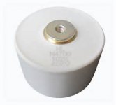
One other fact I'd like to state is, capacitors are also a conductor! (of AC). They are also rated for current, as well as voltage (before breakdown occurs). This could also explain why physically larger capacitors 'sound' better to some astute people. In high powered transmitters for example, inter-stage coupling capacitors need to be rated accordingly for high current (in current sensitive locations). 'Door knob' caps are used here. One could use a high voltage ceramic cap here, but they would over heat and explode! I guess same thing applies at AF frequencies...
We were taught to ALWAYS use units during calculations (F, Ohm, V etc). This makes a lot of sense!
Yea, saturation could occur in a conductor, sort of. Current flowing thru a conductor creates magnetic field around it. Coiling conductor concentrates this. So, I guess resistors saturate Tweet? They loose energy via heat... This is a bit different to 'magnetic saturation' though...
https://en.wikipedia.org/wiki/Saturation_%28magnetic%29
Also heat induces temperature coefficients... Resistance rises with heat... There are devices called 'NTC' and 'PTC' in electronics. One of which is used to protect tweeters from burning out due to 100% duty cycle, ie DC!
One other fact I'd like to state is, capacitors are also a conductor! (of AC). They are also rated for current, as well as voltage (before breakdown occurs). This could also explain why physically larger capacitors 'sound' better to some astute people. In high powered transmitters for example, inter-stage coupling capacitors need to be rated accordingly for high current (in current sensitive locations). 'Door knob' caps are used here. One could use a high voltage ceramic cap here, but they would over heat and explode! I guess same thing applies at AF frequencies...
Attachments
Last edited:
links
Wolf's jig
Winding inductors - Techtalk Speaker Building, Audio, Video Discussion Forum
Bobbins
6PC 38*20mm Plastic Bobbin Wire Coil Former FR DIY Speaker Crossover Inductor | eBay
Clear 28*14mm Plastic Bobbin Wire Coil Former DIY Speaker Crossover Inductor*10 | eBay
4PCS 53*29mm Clear Plastic Bobbin Coil Former FR DIY Speaker Crossover Inductor | eBay
Thanks for the link to Wolf's inductor construction John! I guess one could use an old reel to reel spool!
I am trying to avoid ebay. A bit like me browsing an electronics store. I like to leave my wallet in the car!
As long as the former or 'holder' isn't metal, it won't skew the value. I like using the Thomas & Betts steel-barbed zip-ties, and then dunking the coils into polyurethane to keep them held together well.
Just scratch some enamel off and measure, repeat if it isn't large enough value. The polyurethane will insulate the internal windings, and other layers will be insulated from the previously scathed. That's how I do it, and just use an LC meter.
Have fun!
Wolf
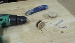
We struggled today to wind inductor without sides self destructing (tight coil wants to force sides outward. Unexpected, to say the least...). So I chose method using dowel (nobody will miss the broom!) and some larger diameter PVC pipe (27mm). This method clamps the former together WITHOUT glue, although glue will be used! I chose to use steal screws, screwed into the dowel. The screws don't penetrate (much, -they don't enter the coil zone, but probably will interact). this is why the ends stick out! The end washers (homemade) clamp the lot together. Hopefully you guy's can figure out how I accomplished this by the photo.
I intend on mounting the inductor inside the cabinet to the wall, as my xover boards are too small!
What do you guy's think??? ps. I was thinking about replacing the two screws with brass ones. Would that work better? Also, I intent on using this point to make some brackets up, may be out of alluminium sheet. then they would serve two purposes!
pps. I like your jig to manufacture inductors Wolf! Very crafty!
So the Sun went down. Shame tomorrows Weather is forecast to be bad. I have leangths of wire running back and forward up and down my drive! Winding onto spool is a PITA. So this is an outdoor job for me!
Attachments
Last edited:
"As long as the former or 'holder' isn't metal, it won't skew the value."
True. Otherwise mag field would induce an electrical current in said inductor")
"Just scratch some enamel off and measure, repeat if it isn't large enough value.'
That is going to be my approach Wolf! I had some practice when winding the 0.36mH inductors. $tuffed up a couple of times..
"Air cored inductances can saturate when the coil's conductance becomes extremely low when approaching the maximum current flow that is able to flow through it.'
That is true Tweet. running 50 amps thru said conductor isn't my goal! I doubt the 35W DIN RMS p/c amp's power supply could deliver this with out self destructing itself! The mains fuse would hopefully blow before whole house burns down! How is your hearing these days Tweet???
Oh and John H. Those links you sent were good, but they were a bit too small for what I am building. I am sure if I searched, I could naturally find larger ones. but I started building formers myself and intend on finishing them!
True. Otherwise mag field would induce an electrical current in said inductor
"Just scratch some enamel off and measure, repeat if it isn't large enough value.'
That is going to be my approach Wolf! I had some practice when winding the 0.36mH inductors. $tuffed up a couple of times..
"Air cored inductances can saturate when the coil's conductance becomes extremely low when approaching the maximum current flow that is able to flow through it.'
That is true Tweet. running 50 amps thru said conductor isn't my goal! I doubt the 35W DIN RMS p/c amp's power supply could deliver this with out self destructing itself! The mains fuse would hopefully blow before whole house burns down! How is your hearing these days Tweet???
Oh and John H. Those links you sent were good, but they were a bit too small for what I am building. I am sure if I searched, I could naturally find larger ones. but I started building formers myself and intend on finishing them!
Last edited:
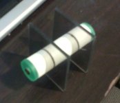
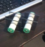
The twin is born. These puppies are vastly superior design. Call them the mark 3. got to wind 1.6mm diameter copper wire on next... Don't even need any gluing.
Very happy. DIY! (I hope they are big enough!)
Very happy. DIY! (I hope they are big enough!)
Attachments
Last edited:
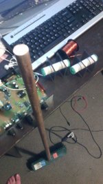
Some reclaimed copper conductor on spool and my new bass processor shown to the left (home wound. Modified Jaycar kit). My poor broom will pull thru all this abuse though!
Kudos jrh0516 (wooden doweling).
Inductors total cost = $0.
Kudos jrh0516 (wooden doweling).
Inductors total cost = $0.
Attachments
Last edited:
I use a pair of 2" diameter heavy steel washers with a 3/8ths bolt through them. One washer needs a small hole drilled through the side to match up with the OD of the spacer and let the start of the wire poke through.
I cut short lengths of plastic pipe to set the cheek to check distance and tighten it all up.
Then I wind on the turns to fill a layer. If it's thinner wire, I wind on a couple of turns of insulating tape or Kapton, to give a fairly level bed for the next layer to sit on.
Using my old rule of 1:1:4 (which may not be best) I usually aim for the cheek to cheek to be half the spacer diam and then the layers should add up to similar to the width. That then gives and overall diameter roughly equal to double the spacer diameter.
Let's turn that into numbers.
Take a 22mm diam plastic pipe and cur to 11mm long.
Bolt up the spool to give a 22mm diameter bobbin with the cheeks set to 11mm.
Wind on 7Turns of 1.6mm wire for first layer. Wind on 7layers. That gives and overall diameter of ~45mm for 49Turns
The bolt is removed the washers are removed.
The spacer is usually tightly stuck in the middle.
I wrap thick cotton/nylon thread in blanket stitch to help hold the turns together.
But I have used 4 to 6 tyraps instead.
- Status
- This old topic is closed. If you want to reopen this topic, contact a moderator using the "Report Post" button.
- Home
- Loudspeakers
- Multi-Way
- Help inductor. Parallel windings of thin wire to make one?