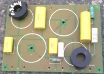
One thing that is often forgotten when using a printed circuit board where the inductor lays flat on the board itself and there is a circular path for current to flow in the copper on the opposite side to the inductor a loss of inductance will occur.
The copper in such a case will represent a short circuit'd winding to the inductor, particularly at high frequencies. How much of a loss ?
This is an excellent point. I hadn't really looked at the board. Apart from the shorted turn issue, mounting several inductors pancake flat to the board can also cause coupling between them. How important this issue is may perhaps be debated. Best to do some searches and see if you can find data on inductor crosstalk or inductor mounting orientation. Even better to test it yourself.
There is an offline version of Coil32 as well...
Download Windows
I am having a play with it. Thanks again !
Download Windows
I am having a play with it. Thanks again !
I did not have time to make up bobbins today. But I have decided to bypass the BP electro's on the boards with 0.1uF Polyethylene caps, three per board. This should lower ESR of caps to high frequencies. Most caps are polys, except for the rather large capacitance ones.
I punched some numbers in and realise we may need to use thicker copper wire! Might make some up from 2 x 20AWG conductors in parallel for $hits and giggles. I am guessing just the bass and mids will be attenuated slightly.
We will space inductors further away from the tracks using ply-wood.
Thanks.
I should of said "Polypropylene Caps".
Anyhow, I have built my 6dB boards up. They were 6dB, but with iron core inductors. I have recycled them (Mr DonVK will like that!). I intend on mounting the 2.54mH inductor remotely, away from the PCB via flyleads. No issue with cross-talk between inductors then!
For 40uF (for mid-range), I paralleled up 2 x 10uF to make 20uF, 2 x 6.8uF, 1 x 4.7uF and 1 x 1uF. Looks a bit messy but better than $hitty electros!
This weekend is meant to be VERY wet here. So no out-door pursuits. Ttime to get these wee projects done!
I do appreciate all whom have contributed!
Photos to follow...
Last edited:
My inductance meter requires new 9V battery. I was going to measure inductance of home-wound 0.36mH inductor before and after mounting to PCB.
Quick question. I was going to bypass electro's with low value (0.1uF) film capacitors to lower total ESR. Question is, with two caps in parallel (electro and film), is bypassing with small value film cap necessary ???
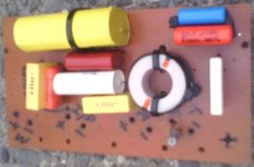
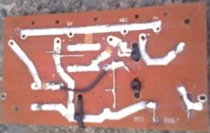
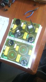
Below are photos of near completed 6dB board (I know it looks rough!) Also, th 2.54mH inductors will be mounted to side of speaker cabinets with fly-leads.
Quick question. I was going to bypass electro's with low value (0.1uF) film capacitors to lower total ESR. Question is, with two caps in parallel (electro and film), is bypassing with small value film cap necessary ???
Below are photos of near completed 6dB board (I know it looks rough!) Also, th 2.54mH inductors will be mounted to side of speaker cabinets with fly-leads.
Attachments
Last edited:
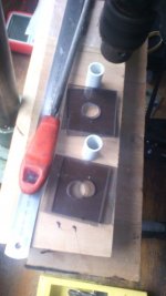
Not a complete success but not a complete failure either! We decided to use square perspex for the sides as this will make it easier to mount AND cut.
I discovered that MS is not good for gluing perspex to the 20mm O.D. PVC (no $hit). I will use Araldite epoxy (EE's never listen to your builder buddy's advice!..)
I am using recycled 0.8mm wire and am doubling it up with mild twist in it to hold it together. This makes 1.6mm over all diameter. Calculated total resistance is < 0.5Ω, so within my desired tolerance.
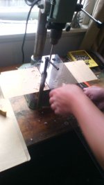
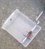
My winding box however works, miraculously! Wires are fed thru rubber grommet. Propulsion is 'Armstrong' method. The blinking %$@#$% sides fell off as the silicon is rubbery...
I discovered that MS is not good for gluing perspex to the 20mm O.D. PVC (no $hit). I will use Araldite epoxy (EE's never listen to your builder buddy's advice!..)
I am using recycled 0.8mm wire and am doubling it up with mild twist in it to hold it together. This makes 1.6mm over all diameter. Calculated total resistance is < 0.5Ω, so within my desired tolerance.
My winding box however works, miraculously!
Wires are fed thru rubber grommet. Propulsion is 'Armstrong' method. The blinking %$@#$% sides fell off as the silicon is rubbery...Attachments
Last edited:
Very nice. Odds & Ends, it's all fair game.
If you put a paper tube + tape over your winding rod (before winding) it may be easier to remove the coil (slides off) after its wound. It would also allow you to temporarily tape the square sides to prevent coil egress as you wind the coil.
I'm interested in the actual measured inductance vs calculated.
Are these capacitors in series with your speaker (pass capacitors for mids or highs) "maybe" ESR is important. If you're paralleling a fistful of caps you're already lowering the ESR + ESL.My inductance meter requires new 9V battery. I was going to measure inductance of home-wound 0.36mH inductor before and after mounting to PCB.
Quick question. I was going to bypass electro's with low value (0.1uF) film capacitors to lower total ESR. Question is, with two caps in parallel (electro and film), is bypassing with small value film cap necessary ???
Below are photos of near completed 6dB board (I know it looks rough!) Also, th 2.54mH inductors will be mounted to side of speaker cabinets with fly-leads.
If they are used as shunt capacitors (woofers) then I wouldn't worry at all.
Hi DonVK.
"Very nice. Odds & Ends, it's all fair game."
Yes ya win some and also loose some! Learning all the way.
"If you put a paper tube + tape over your winding rod (before winding) it may be easier to remove the coil (slides off) after its wound."
Good idea! That way paper tube locks spool in place (I used PVC insulation tape in a pinch with poor results!) and is easily removed.
Egression was symptomatic. Basically the perspex squares fell off. I expected no less as I observed very "floppy" sides! I dig that (non stretchable, paper tape) could be used to keep form. Good thinking 99! Afterwards, coil could be contained with cable ties.
Microphonics and rigidity is key. Shake baby shake! Ringing is bad. I could lower 'Q' with padding resistor, but why bother...
"I'm interested in the actual measured inductance vs calculated."
Stolen fruit always tastes better! I am too mate. Using calculator to obtain "50M wire length" is pure trivia. Measure once, cut twice. Nah, the other way around! I am grouping twin conductor in 15M lengths for $hits and giggles, then splicing to reach total of ~ 50M.
My trusty LC inductance meter will then play a part.
Network analysis might be fun mathematically, but I prefer to clean my belly button out!
Estimated vs Calculated vs Obtained Value is what I'd like to compare! I miss my speakers and amp! Listening to my PC monitor is really bad. All them surface mounted components!
I also sport a Plinius III (the first!) and a Leak 20. My main amp is a Technics amp from the early '90's. Quasi class A, so no (little) crossover distortion (sort of!).
I will shoot photos of my setup and mates setup soon !
Bless FLAC. I am not much of religious person, but got to preserve quality, right? Life is short!
"Are these capacitors in series with your speaker (pass capacitors for mids or highs) "maybe" ESR is important. If you're paralleling a fistful of caps you're already lowering the ESR + ESL.
If they are used as shunt capacitors (woofers) then I wouldn't worry at all."
I have read the capacitor thread on this forum. Very interesting. I am aware of what ESR is (equivalent perfect resistor in parallel with cap) and ESL (series inductance due to construction, leads etc. 'Complex circuit'! which is always fun to analyse...
I posted the question BEFORE reading the cap thread here...
http://www.diyaudio.com/forums/multi-way/78568-tony-gees-capacitor-page-updated.html
Seems like an interesting topic... I guess One should not just swap out caps and be happy... Unless One gets lucky.
Might have to crank up sweep generator later (after completion) with full-range mic attached (test that first!) and look on scope to see how flat things are. Filter crossover points etc. Still, I am at 'novice' grade really. I do appreciate music and My Leak 20 has really nice sounding midrange (valves baby!). Bass is a little quiet and treb is a bit grainy, but mid-range has me smiling! Listen to some old psychedelic Pink Floyd and close Ones eyes! Instruments sound spaced distance wise away from one another and 'separate'. Is very nice "musical" sounding.
But anyhow, more to come.
Last edited:
I'm not a big fan or believer of $35 esoteric caps specifically marketed to the HiFi crowd. If it makes you feel good then go for it. The highest up the chain I'll go is $2 Polyester caps for series and non-pol electrolytics for shunts. I'd probably even use electrolytics with a parallel poly for midranges as well. Using economy caps has never been an issue for me in audio (low freq) applications. If you had tuned RF circuits, or high speed digital circuits or switch mode power supplies then you would need very different and specialized capacitors.
This is a good start.DCR calculation is simple. The wire has X resistance per Meter.
Today (very soon) my mate is coming over with perspex sheet and hole cutters. We are using 20mm O.D. PVC pipe for the former.
More to come")
Using your 20mm bobbin set the width cheeks about 10mm apart.
Now wind on your inductor till you reach an outer diameter of 40mm.
Thus you end up with a 10mm long inductor that is 40mm diameter and the cross-section of wire is roughly 10mm by 10mm.
You will find that this 1:1:4 coil height : coil length : Overall diameter gives very close to the minimum resistance for the inductance achieved, i.e. highest Q value. eg. using 1mm diameter wire wind on 10 turn per layer and use 10layers for a total of 100Turns.
Using a smaller bobbin diameter will result in a higher resistance, no matter how you change the height and length and number of Turns for that 1mm wire diameter.
DonVK Yes I read somewheres to not use electros above ~10KHz, which makes sense. I don't want to start a war over cap types here! but all this teflon, copper, silver stuff is nonsense!!! Conductors are just that. They conduct electrons. I am aware of what skin affect is. This occurs at above something like 500MHz to 1GHz. Miles above audio range for humans! This is where silver comes into play as silver is the only (don't quote me) metal that's oxide is actually conductive.
One could get better value by cleaning wax out of ones ears!
I do however try to use film caps at all cost. LL electros won't be too bad. As my mids are set to 500Hz to 5000Hz (with -6db per octave) [octave is basically f x 2] electros should be fine, in theory.
I agree with fact of no cap is better than any cap! My Plinius III is DC coupled amp. All good till a device fails! (bang!)
i/p and o/p impedance match is very important. Best transfer is done when impedances match (max energy transfer). This might explain why different cables make a difference (I must test this myself, different cables to be sure). I just use thick red/black copper cable.
Bypassing electros with film is not a bad idea, if > 10KHz signals will flow thru. May be 100nF or 10nF.
Just my 5c on the subject!!!
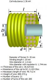
Andrew T see post # 48 of mine. Basically I am using 20mm diameter former (pipe) and spaced "cheeks" at 25mm. This gave lowest DCR (resistance) according to Coil32. As Mr. DonVK stated, I'd like to know final DCR myself! I hope it will be < 0.5 ohm (DC) as this is in series with 8 ohm (impedance) woofer. This resistance of 0.5 ohm will need to be factorised. Obviously this will attenuate the woofer somewhat. I already know that my woofer is less sensitive compared to my mid, and especially my tweeter! so low DCR is very important, otherwise I will need to attenuate mid and tweeter quiet a lot, thus lowering efficiency of my 3 way speakers!
"You will find that this 1:1:4 coil height : coil length : Overall diameter gives very close to the minimum resistance for the inductance achieved, i.e. highest Q value. eg. using 1mm diameter wire wind on 10 turn per layer and use 10layers for a total of 100Turns."
Interesting. I will dial this into Coil32 and see. I of course need 2.54mH, so I may have to fiddle with the # turns p/layer, I guess?
Thanks Gents ! Went out on 106km dirt bike ride today so having fun out in NZ outback !!!!
One could get better value by cleaning wax out of ones ears!
I do however try to use film caps at all cost. LL electros won't be too bad. As my mids are set to 500Hz to 5000Hz (with -6db per octave) [octave is basically f x 2] electros should be fine, in theory.
I agree with fact of no cap is better than any cap! My Plinius III is DC coupled amp. All good till a device fails! (bang!)
i/p and o/p impedance match is very important. Best transfer is done when impedances match (max energy transfer). This might explain why different cables make a difference (I must test this myself, different cables to be sure). I just use thick red/black copper cable.
Bypassing electros with film is not a bad idea, if > 10KHz signals will flow thru. May be 100nF or 10nF.
Just my 5c on the subject!!!
Andrew T see post # 48 of mine. Basically I am using 20mm diameter former (pipe) and spaced "cheeks" at 25mm. This gave lowest DCR (resistance) according to Coil32. As Mr. DonVK stated, I'd like to know final DCR myself! I hope it will be < 0.5 ohm (DC) as this is in series with 8 ohm (impedance) woofer. This resistance of 0.5 ohm will need to be factorised. Obviously this will attenuate the woofer somewhat. I already know that my woofer is less sensitive compared to my mid, and especially my tweeter! so low DCR is very important, otherwise I will need to attenuate mid and tweeter quiet a lot, thus lowering efficiency of my 3 way speakers!
"You will find that this 1:1:4 coil height : coil length : Overall diameter gives very close to the minimum resistance for the inductance achieved, i.e. highest Q value. eg. using 1mm diameter wire wind on 10 turn per layer and use 10layers for a total of 100Turns."
Interesting. I will dial this into Coil32 and see. I of course need 2.54mH, so I may have to fiddle with the # turns p/layer, I guess?
Thanks Gents ! Went out on 106km dirt bike ride today so having fun out in NZ outback !!!!
Mine (Ours) will be 37 : 25 : 94. I don't feel like simplifying that ratio too much! (My poor brain), but according to Coil32, this is best. I factorised spacing of "cheeks" into software, with constant of 20mm "tube" O.D. Software churned out highest 'Q' (quality baby!) with said ratio...
Oh I love how "text book" and "real world" stuff collide! Keeps Us young (or bald / anxious! Take your pick!!!!)
As 'The Doobie Brothers' said "Listen to the music!"...
Oh I love how "text book" and "real world" stuff collide! Keeps Us young (or bald / anxious! Take your pick!!!!)
As 'The Doobie Brothers' said "Listen to the music!"...
Hi Butcher greeting from across the "ditch".
Re: "feet and inches" from your earlier post.
This is PURE trivia but you may enjoy it....if you follow cricket. I heard that a few years ago that the first game of a new season of Grade cricket at a Sydney suburban ground was proving very frustrating. There were a lot of "short" balls and may be an unexpected run out.
The pitch turned out to be over 24 yards long! The story is that the new Vietnamese groundsman had got the "22" bit correct but measured it off in Metric and not Imperial unit and it was 10% too long.
Cheers Jonathan
Last edited:
"I must say Butcher you're a dedicated man.
Are you going to make your own capacitors too ? ......out of Alfoil and lunch wrap ?"
No, I bought them from a store! Actually an aussie one (Jaycar). They had a beer tap and a shiela in there whom was singing Waltzing Matilda !!! HAHA.
My Friend bought all new caps. I recycled mine. Well, I bought the 10uF caps for mine from Jaycar too. No change from $40! Making my own coils is, how we say down under as "bloody cheap!" (just like me!) Plus Jaycar over here have gone out of stock. I enjoy adding a bit of blood sweat and tears to my designs. And I learn something along the way. Someone whom "builds" there own stuff from shop stock is missing out on half the fun. As the old saying goes, "wind your own"...
A friend of mine made His own variable capacitor. Part of an impedance matching network on a 160M band CW transmitter. It comprised of perspex, a spring, a screw and some sort of sheet metal (?) Probably left over tin foil from the bbq? I was blown away! It worked fabulously.
Also, creating ones own high voltage capacitors is not that hard. Neutralising caps in valve (tube) AM broadcast band transmitters, for example!
"Hi again Butcher. Re: #56. Your comment reminds me of a lovely quote from Gilbert BRIGGS book on loudspeakers (5th Ed). it is a cynical German proverb.......which in English is...
"When theory and practice agree.............both are wrong!""
Hello! I surprise myself sometimes! I still often put my tee shirt on back to front though!
I am glad us 'sophisticated' folk down under here adopted metric system as far back as 1969 (or was it '67?). Before my time by a decade... Was it the Hubble telescope project, the Germans manufactured something in metric? instead of imperial? Never mind. I was taught both ways. Imperial works good in fractions, but I digress...
"When theory and practice agree.............both are wrong!"
Such a lovely quote! Have I mentioned "Murphy's law" yet? That one is so true...
Last edited:
- Status
- This old topic is closed. If you want to reopen this topic, contact a moderator using the "Report Post" button.
- Home
- Loudspeakers
- Multi-Way
- Help inductor. Parallel windings of thin wire to make one?