Very nice, ECO green reuse.
It's already "magnetics wire" which has insulation (varnish) so it can be repurposed. I'm assuming you're making an easy air bobbin style and not attempting a torroid. If I could get a supply of magnetics wire at reasonable price and qty I would wind my own as well.
You can parallel the strands, and resistance will decrease (like all parallel resistors) and current capacity will increase assuming you properly solder them at both ends. Do you actually need more capacity or lower resistance than 18awg? The effective capacitance increase will be minor because you have the same potential on both sides of the insulator (varnish) meaning no "E" field differential and no charge transfers. Its easy to determine the equivalent wire gauge via cross section area of 0.823mm^2 for a single 18awg so 2 of them is 1.65mm^2 or equivalent to a 15awg and so on https://en.wikipedia.org/wiki/American_wire_gauge.
Twisting is fine in moderation, but it does make the strands longer than the twisted pair length. You could also attach your bobbin to the drill and use it to wind the inductor as well. You can "guesstimate" the size of coil and it's resistance using manufacturers existing sizes (ID, OD, height, resistance) just look it up in the their tables. (http://solen.ca/wp-content/uploads/stdind.pdf) You could also use one of the many calculators, but I would still check it against an actual one.
Winding calculator sites
Shavano Music Online - Cross-Over Network; Air Core Inductor Calculator
Pronine Electronics Design - Multilayer Air Core Inductor Calculator
An introduction to the air cored coil
I use an electric drill with a wooden axle to help wind. There are a number of plastic forms/ bobbins you can get from EBay. I’ve also made wooden forms
"in that case, inductance will come mainly from amount of turns, and core diameter , while DC resistance will be directly proportional to wire length and inversely proportional to number of strands in parallel, which will dictate equivalent wire section."
Yes, thanks JMFahey. I may loosely wind three strands together for a start. Rt (total resistance should not increase too much. Loose winding will keep things a bit neater. All three strands will be equal length.
"But if you need to make stranded wire DO NOT US A DRILL it is not the way to go."
audiofan Thanks. I intent on using few twists as possible.
Thanks nigelwright7557. I am concerned about capacitance and its affect on sound. I guess at 500Hz and below, capacitance (inter winding) would me insignificant as far as Z goes (inductance).
"Hi Butcher, me again, I though you were in Australia, a mix up with the flags.'"
Careful our NZ airforce will send planes over !!!! Haha. Yes, I am in fact kiwi! (flag confusion, get your eyes checked digga!) hahaha. (Kiwi and Aussie joke. I am glad we kept our lovely flag. But lets keep to topic!)
"Heavens, they should just build a bridge between the two countries and be done with it."
Haha. What do you call a sophisticated Australian? A kiwi !!!! lol.
"Actually, non-inductive resistors generally provide very little benefit in passive crossovers because the audio frequencies are too low, any inductive reactance of a normal wire wound resistor likewise is essentially trivial at audio frequencies so making your own is likely to have inaudible results."
I measured a 1Ω (I think it was) wire would resistor and read about 1mH. that is quiet high. I am pretty sure the measurement was correct. The DC part should not matter. I might crack open the resistor and see how it is wound.
"If you were to make an iron cored inductor it is best not to use nails or ordinary iron parts as they tend to have high retentivity and poor permeability. Audio transformer cores are best suited for the purpose if you decide to make your own laminated iron core inductors. Just a few thoughts."
Yes, laminated iron to decrease eddy currents, if I am not mistaken. I suspect the laminates are dipped in enamel to form insulated layers (?). I don't care if the inductors are as big as oranges, space is no problem!
Thanks Tweet.
I have seen may formulas for estimating solenoid inductance. I would like to know roughly how large these inductors will be.
"If you need to calculate inductors look for '' weeler formula'' & '' brooks coil ''."
I will research this. Math is no problem for me as I studied electronics. Took me a while to get my head around math though (and lots of aspirin!).
So, air core it will be. I may parallel up three (or 4?) strands of 0.8mm wire at lengths of say 10M. then I will join together by solder. Then I can attach further lengths and measure total inductance. I can then fine tune them.
Any advice on what diameter to make the center? My 0.36uH ones use about 18 or 20mm. Can this be reduced to say, 5 - 10mm? This would make the larger (high inductance) inductors slightly smaller. I indend on securing these large inductors in home made bobbins with MS (silicon) and cable ties.
Also, can someone suggest rough dimensions of these inductors? (1.8mH and 3.6mH). I indent on using circular bobbins with height being 1/2 that of width.
Today I intend on doing some experimenting... Thanks for advice on using nichrome wire as resistors. I can obtain for free from old heaters etc. I might just use 3 or 5W metal film types from a store...
Thanks.
"Very nice, ECO green reuse."
Thanks. Saves copper being melted and reused! Bad for our environment (and pocket!)
somewhere I have data on phase 1 to phase 6 fisher and paykel washing machine motor copper wire diameter. Data is on my PC somewhere. When I find it, I will share.
I suspect some use 1mm, or even 1.2mm wire (?)
Thanks DonVK and jrh0516 for the info!
More to come...
Re Fisher and paykel washing machine motor copper wire diameter...
Series 60, 80 and 100 series stators...
60 series = 0.6mm
80 series = 0.8mm
100 series = 1mm
The early models (series 1?) uses the 1mm diameter wire. These machines were around in the early 90's and made in New Zealand.
So looks like the series 100 motors would be good candidate! I got a shite load of magnet wire from the 80 series motor. I do have some 100 series motors in storage at a mates place...") I hope this info will help someone out. There is lots of info on creating windmill motors using these f&p washing machines... (see google).
I hope this info will help someone out. There is lots of info on creating windmill motors using these f&p washing machines... (see google).
Thanks.
Series 60, 80 and 100 series stators...
60 series = 0.6mm
80 series = 0.8mm
100 series = 1mm
The early models (series 1?) uses the 1mm diameter wire. These machines were around in the early 90's and made in New Zealand.
So looks like the series 100 motors would be good candidate! I got a shite load of magnet wire from the 80 series motor. I do have some 100 series motors in storage at a mates place...
I hope this info will help someone out. There is lots of info on creating windmill motors using these f&p washing machines... (see google).Thanks.
Neatness is important because the further a turn is from the core, the longer the wire used. It would be a shame to have your gauge compensating for this. I would suggest calculate the inductor and specifying an allowable resistance to see if you can do it with something you already have. If you have ever tried to wind one off inductors bifilar without twisting you'll know it may get difficult.So, air core it will be. I may parallel up three (or 4?) strands of 0.8mm wire at lengths of say 10M. then I will join together by solder.
That would indeed be high.I measured a 1Ω (I think it was) wire would resistor and read about 1mH. that is quiet high.
The parasitic inductance and capacitance in wire wound resistors are quite low (<10R, uH, pF) and should not be a concern for audio frequencies. I've read a number of threads confirming this, unfortunately they are buried in other topics and I don't have them at hand. Look at it like this, if you could buy a $0.5 resistor and use it as a 1mH inductor it would be a bargin
http://www.resistorguide.com/inductance/
http://www.resistorguide.com/inductance/
Um yes, mine read about 0.8 - 0.9uH.
So not 1mH but 1uH! I was only 3 decimal places off!
I was reading resistors of approx 1Ω to about 4Ω7. So it looks like I will be using w/w resistors afterall. I have spaced them off of the PCB so as to allow them to not get too hot or resistance will increase.
I am using a 33Ω resistor as part of tweeter attenuator (simple potential divider circuit for -2dB). I will measure that resistor as I presume it will have more windings. I guess higher wattage resistors use thicker wire and possibly less windings (? probably not less windings though).
I intend on 'upgrading' to metal film resistors eventually. I guess w/w resistors are not as noisy as carbon composite types!
Today me and my friend will be making bobbins for the large inductors. I will share some photos of our creations soon (I guess you folk like pictures?!).
Thanks for your i/p Folks!
Last edited:
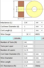
So after finding some spare time, I discovered that winding coil with very small ID is the way to go (ie. not winding on an 18mm former, but 1mm). I punched some data into air-wound inductor calculator and ascertained optimal results for 2.54mH.
Am I on the right track? (Just figuring out how to upload images...)
Tomorrow I play! I am going to use piece of wire (s/s) as former and use stiff cardboard for a guide...
Am I on the right track? (Just figuring out how to upload images...)
Tomorrow I play! I am going to use piece of wire (s/s) as former and use stiff cardboard for a guide...
Attachments
Read up on the Brooks ratio or scroll down to the of Multi layer coil here An introduction to the air cored coil
Even though inductance favours a tiny radius I would go bigger. Minimum initial bend radius should be at least 6x wire diameter. So 20awg is 0.812mm diameter so a safe min core ID is 5mm (or larger). Trying to bend a 0.8mm wire on a 1mm core will take a lot of force, stress the wire, maybe cracking the outside surface.So after finding some spare time, I discovered that winding coil with very small ID is the way to go (ie. not winding on an 18mm former, but 1mm). I punched some data into air-wound inductor calculator and ascertained optimal results for 2.54mH.
Am I on the right track? (Just figuring out how to upload images...)
Tomorrow I play! I am going to use piece of wire (s/s) as former and use stiff cardboard for a guide...
I was thinking last night about using may be a 5mm fiberglass rod (felt pen?!). But keeping the inner core small greatly increases the inductance but keeps the DC resistance down. Ya can't avoid ohms law!
Thanks for the link John. Looks interesting. In that text it said "the winding should have a square cross section.". Interesting.
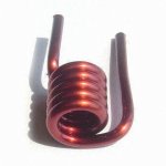
And Don, "Trying to bend a 0.8mm wire on a 1mm core will take a lot of force, stress the wire, maybe cracking the outside surface.". Yes but many VHF / UHF single layer coils are wound thus. Shown is what looks to be a DC choke wound in very thick wire! I will follow both your guidance and use 5 or 10mm core.
More to follow (hopefully a working prototype). "I am not about to reinvent the wheel!"
And according to my number crunching, 0.8mm wire should be sufficient. 1mm wire has 1/2 the resistance though. I have to pick up my f&p washing machine motor with the 1mm wire at some stage.
Thank you.
Thanks for the link John. Looks interesting. In that text it said "the winding should have a square cross section.". Interesting.
And Don, "Trying to bend a 0.8mm wire on a 1mm core will take a lot of force, stress the wire, maybe cracking the outside surface.". Yes but many VHF / UHF single layer coils are wound thus. Shown is what looks to be a DC choke wound in very thick wire! I will follow both your guidance and use 5 or 10mm core.
More to follow (hopefully a working prototype). "I am not about to reinvent the wheel!"
And according to my number crunching, 0.8mm wire should be sufficient. 1mm wire has 1/2 the resistance though. I have to pick up my f&p washing machine motor with the 1mm wire at some stage.
Thank you.
Attachments
Last edited:
So after finding some spare time, I discovered that winding coil with very small ID is the way to go (ie. not winding on an 18mm former, but 1mm). I punched some data into air-wound inductor calculator and ascertained optimal results for 2.54mH.
Tomorrow I play! I am going to use piece of wire (s/s) as former and use stiff cardboard for a guide...
That calculator uses this formula
currentInd = ( diamavg / 1000.0 ) * diamavg * turns * turns / (( 18.0 * diamavg ) + ( 40.0 * coilLen ))
Generally such a simple formula will make assumptions on coil proportions that do not include a 1mm core and 8turns x 31layers
The only references I can find to coil formulas using 18 and 40 are for single layer coils, so that calculator is probably bunk.
I plugged your values into a calc I wrote and got <1mH, but about the same resistance calc.
For a 20 gauge ~2.54mH coil I get:
263 turns
Core Diameter 1.1604 inches
Coil length 0.5526 inches
Coil Diameter 2.1551 inches
Wire Length 1369.72 inches
Wire Length 114.14 feet
ohms/inch 0.0008
resistance 1.159 ohms
weight 0.36 lb
Last edited:
Feet and inches eh? !
I was wondering if the calculator I used was a little bit dodgy. Images I have seen of coil shape all seem to look like Brooks work.
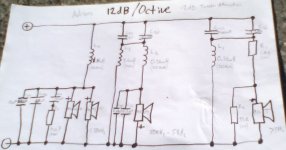
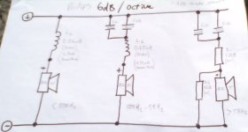
I am kind of trying to keep coils O.D. at 60mm (2.36") due to PCB size. This is for the 12dB/Octave boards. This board calls for 1.8mH and 3.6mH inductors for the LP and BP respectively. I am also designing a 6dB/Octave board for myself. This uses a 2.36mH inductor for the LP. I really should at this point upload photo of my boards...
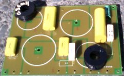
Below is photo of the 12dB/Octave board / circuit and 6dB/Octave circuit.... (I also intend in preventing as much as possible cross-talk between coils. I will mount out of plane as much as possible (at right angles).
I was wondering if the calculator I used was a little bit dodgy. Images I have seen of coil shape all seem to look like Brooks work.
I am kind of trying to keep coils O.D. at 60mm (2.36") due to PCB size. This is for the 12dB/Octave boards. This board calls for 1.8mH and 3.6mH inductors for the LP and BP respectively. I am also designing a 6dB/Octave board for myself. This uses a 2.36mH inductor for the LP. I really should at this point upload photo of my boards...
Below is photo of the 12dB/Octave board / circuit and 6dB/Octave circuit.... (I also intend in preventing as much as possible cross-talk between coils. I will mount out of plane as much as possible (at right angles).
Attachments
Last edited:
Feet and inches eh? !
I was wondering if the calculator I used was a little bit dodgy. Images I have seen of coil shape all seem to look like Brooks work.
I am kind of trying to keep coils O.D. at 60mm (2.36") due to PCB size. This is for the 12dB/Octave boards. This board calls for 1.8mH and 3.6mH inductors for the LP and BP respectively. I am also designing a 6dB/Octave board for myself. This uses a 2.36mH inductor for the LP. I really should at this point upload photo of my boards...
Below is photo of the 12dB/Octave board / circuit and 6dB/Octave circuit.... (I also intend in preventing as much as possible cross-talk between coils. I will mount out of plane as much as possible (at right angles).
One thing that is often forgotten when using a printed circuit board where the inductor lays flat on the board itself and there is a circular path for current to flow in the copper on the opposite side to the inductor a loss of inductance will occur.
The copper in such a case will represent a short circuit'd winding to the inductor, particularly at high frequencies. How much of a loss ?
I just happen to notice the indicated placement of a large coil on your printed circuit board. Best to stand it in a vertical position I would think.
C.M
Last edited:
Thanks Ron E! Did you write that calculator?? I will punch some numbers into it after tea...
"One thing that is often forgotten when using a printed circuit board where the inductor lays flat on the board itself and there is a circular path for current to flow in the copper on the opposite side to the inductor a loss of inductance will occur.
The copper in such a case will represent a short circuit'd winding to the inductor, particularly at high frequencies. How much of a loss ?
I just happen to notice the indicated placement of a large coil on your printed circuit board. Best to stand it in a vertical position I would think."
Interesting. I wonder how much difference that would make? I guess my trusty inductance meter (Jaycar / Silicone Chip) could measure it? Also, I'd be curious how far out the magnetic flux would travel outside of the coil? (I have seen the images of where the flux lines occur). This would not be much of an issue with iron core inductor, as field would be circulating much closer in. As I have not soldered the 0.36mH inductors in place, I could mount above board with wooden or plastic spacers. We intend on using MS (type of silicon) to mount inductors to prevent vibrations shaking the assy. I can't imagine much microphonics being generated in the inductors, but you never know. I may just use MS and cable ties with my one...
But really good point. I think when tuning the 0.36mH ones, I noticed a little bit of a change in measured inductance when measuring after removing turns to fine tune... I think about 0.03mH or so per turn. I realise that the N^2 ratio comes into play though (not as simple as that!)...
So yes, progress. We have obtained some perspex and some PVC pipe for the inner part. I figure we will need to use 18AWG wire to keep DC resistance down, especially for the 3.6uH and possibly the 2.36mH inductors. I might use twin 20AWG wire for my 2.36mH inductors to half 'R'.
I plan on making 6dB / Octave crossover for my speakers first and then a 12dB / Octave crossover and doing an A / B test
Thanks Tweet.
Last edited:
Thanks Ron E! Did you write that calculator?? I will punch some numbers into it after tea...
No, but it is one of the highest quality calculators I have seen. One quibble I have with it is that the automatically calculated insulation thickness seems rather large, but I haven't thoroughly evaluated it.
My calculator uses simpler wheeler formulas, and is reasonably accurate, although something seems a little off with the resistance calc in the example I posted. Another calc I have that works a little differently gives a better value of ~1.21 ohms or so for the same coil.
Most of the calculators online are javascript toys and many are copies of each other. They are easy to plagiarize since you only have to view source on the page to get the code.
- Status
- This old topic is closed. If you want to reopen this topic, contact a moderator using the "Report Post" button.
- Home
- Loudspeakers
- Multi-Way
- Help inductor. Parallel windings of thin wire to make one?