stupid VAS
Hi Olivier,
Of course I had a look at BV approach, but his solution, among a dozen other ones, has the disadvantage that the gain of the VAS is greatly reduced.
Well, the basic concept of my CMCL is not obsolete, rather the rest of the design, that is, for example the CFB output stage. Also the input stage can be made much simpler by using a high performance IC like AD796, LME49860, or so (have a look at the Alexander amp).
As for the opto-coupler concept, I think nothing nothing wrong with that (in principle), although most opto-couplers have a limited bandwidth.
Hmm... difficult question. I'm inclined to reject all Slone's ideas, as his ill conceived complementary VAS circuitry clearly demonstrates a serious lack of basic knowledge of electronics.
Met vriendelijke groet,
Edmond.
Hoi Edmond Stuart,
Did you check BV's modification to my base circuit? He splits one of the degenaration resistors of the Current Mirrors then instead of feeding the VAS directly by the rail voltage it gets its current through one of the split resistors in the CM circuit.
Is this just another method of CMP (simple one) or is this a completely different approach? And which is best?
Hi Olivier,
Of course I had a look at BV approach, but his solution, among a dozen other ones, has the disadvantage that the gain of the VAS is greatly reduced.
Thnx for the circuit anyway. When you say CMP is obsolete you mean the optocoupler thing right? Or do you mean the Slone Amp?
Well, the basic concept of my CMCL is not obsolete, rather the rest of the design, that is, for example the CFB output stage. Also the input stage can be made much simpler by using a high performance IC like AD796, LME49860, or so (have a look at the Alexander amp).
As for the opto-coupler concept, I think nothing nothing wrong with that (in principle), although most opto-couplers have a limited bandwidth.
Is it a good idea to use Slone's approach and try to eliminate the VAS stability problem by any means or does any attempt to coop with the problem reduces the whole concept to something worse than other - simpler circuits?
Would you build Slones one like I try (with needed mods)?
Beste Groeten,
Olivier
Hmm... difficult question. I'm inclined to reject all Slone's ideas, as his ill conceived complementary VAS circuitry clearly demonstrates a serious lack of basic knowledge of electronics.
Met vriendelijke groet,
Edmond.
Hi there,
You say it greatly reduces VAS gain? Why is that and how much is greatly?
Am I right to say that it gets reduced by the fact that there is now a 5 or 10 ohms resistor in the emiter leg of the VAS? And this is multiplied by HFE say 100 becomes lets say 750 ohms in parallel with the Emiter resistance of the Darlington device which for me is 182 Ohm but SLone uses often 100 or 220. If it were 100 the total value would drop to 90 ohm times HFE say 100 -> 9K input resistance of the VAS loading the IS. If there is no resistor in the VAS emiter leg it would be just Re' say 2ohms times 100 is 200 in parallel with the 100ohm emiter resistor of the darlington Q. Giving 67 ohm times 100 = 6,7K input resistance of the VAS loading the IS.
Is this so bad?
BV what do you think?
Edmonds what do you think?
Greetz
In his latest version of the Audio power amp design handbook, Self briefly mentions mirror image VAS stages. While he does mention that there are definite benefits to using them (along with the mirrored input stage), they are difficult to realise, simply because the standing current through the VAS (and bias generator) is undefined. And as a result of this it could lead to spontaneous combustion.
Olivier,
I have done a lot of Spice work on an input stage with the same topology (unfortunately building it has been on hold for a while.) As already discussed the VAS current is undefined, I did the same experiments as you did in simulation with 1% changes in values showing huge changes in VAS current.
The options are 1) ditch the current mirrors or 2) figure out a way to get the VAS current defined. Since the current mirrors have a huge benefit in reducing distortion I tried various approaches to 2). The other threads already mentioned were a huge help in understanding the issue and developing a solution. Two possibilities that I explored in detail:
a) loading each side of the VAS with a current source - I rejected this because of added complexity (the current sources) and because I wanted a differential VAS, somehow separating it and adding the current sources offended my sense of aesthetics.
b) defining the voltage at the base of one side of the VAS. There are various ways to do this, what I settled on was using a resistor divider off the voltage at the base of one of the current sources that loads one side of the input diff pair (in your schematic, Q9) to generate the desired voltage, then connecting it via a 1K resistor to the base of one side of the VAS (Q11.)
Of course this is all in simulation, but with this solution I found that the sensitivity to slight changes in component values was for all practical purposes eliminated, and there was only a slight penalty in added distortion. Another thing to look at in simulation is the power-on behavior as the voltage supplies ramp up.
Hi 5th & Mightydub,
Welcome to the club")
We agree the VAS current is undefined. A 1% tolerance on the component parameters causes the VAS to Cut-Off (class C) or to grill out. Even if one tries to play with tolerances and eventually succeeds in setting up a nice Iq for the VAS it wil sure certainly run away soon due to temperature effects. I already tried to tyrape the Diff Q's and CM Q's back to back together to reduce differential temperature between them and it helps a bit but it still 'sucks' (sorry).
Mightydub, did you check BV's solution? I find it quite elegant. Take a look and let me know. I will try simulations on yours too...
See you tomorrow guys...
Welcome to the club
We agree the VAS current is undefined. A 1% tolerance on the component parameters causes the VAS to Cut-Off (class C) or to grill out. Even if one tries to play with tolerances and eventually succeeds in setting up a nice Iq for the VAS it wil sure certainly run away soon due to temperature effects. I already tried to tyrape the Diff Q's and CM Q's back to back together to reduce differential temperature between them and it helps a bit but it still 'sucks' (sorry).
Mightydub, did you check BV's solution? I find it quite elegant. Take a look and let me know. I will try simulations on yours too...
See you tomorrow guys...
I looked at BV's solution, still thinking about it.
My solution is really simple - with the input grounded, determine the voltage on the base of Q11. Create a voltage source to match and attach it to the base of Q11 via the largest resistor you can use but still keep the VAS current stable with variations in components. You can see the details here: http://www.diyaudio.com/forums/solid-state/153639-update-aragon-4004-a.html
My solution is really simple - with the input grounded, determine the voltage on the base of Q11. Create a voltage source to match and attach it to the base of Q11 via the largest resistor you can use but still keep the VAS current stable with variations in components. You can see the details here: http://www.diyaudio.com/forums/solid-state/153639-update-aragon-4004-a.html
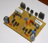
1 year ago I build an amplifer bassed in Randy´s amp, my 3rd amp.
- Input cascode with current mirror
- VAS cascode
- pair TIP3055/2955 no Sanken...
- Output stage with gain x2
- I use this amp with output inductor + R
- Input cascode with current mirror
- VAS cascode
- pair TIP3055/2955
no Sanken...- Output stage with gain x2
- I use this amp with output inductor + R
Attachments
Why do you need a current mirror load on the front end LTP's in a fully blanced design? Its fairly easy, if you use a resistive load, to adjust this value in simulation so that the current in the two LTP transistors is balanced and distortion is nulled. Secondly, with a resistive LTP load its quite easy to acheive >50dB of loop gain at 1KHz and 30dB at 20KHz for class 20KHz AB distortion of <10ppm into 8 Ohms at 100W. Most importantly, there are no VAS balancing issues - the amp centres and there are no rail stick issues either - all significant issues with fully balanced symmetric designs that attemp to use mirror loads on the LTP.
I guess it's important to make it more complicated; furthermore, why use a cascode on the input pairs, is it really necessary, aside from improving the thd (and even that is a moot point), does it actually improve the sound? The rails are just 27V, so it's not necessary to use special transistors on the LTPs.....
However, everyone does it differently, we should be tolerant. I'm sure Randy had his reasons.
Hugh
However, everyone does it differently, we should be tolerant. I'm sure Randy had his reasons.
Hugh
Hi there,
You say it greatly reduces VAS gain? Why is that and how much is greatly?
Hi Olivier,
The VAS gain is reduced by the local NFB loop, i.e. from the VAS emitter back to the current mirror.
Depending on the VAS output load, this gain reduction amounts something between 20 and 40dB (compared to the CMCL approach).
Am I right to say that it gets reduced by the fact that there is now a 5 or 10 ohms resistor in the emiter leg of the VAS? And this is multiplied by HFE say 100 becomes lets say 750 ohms in parallel with the Emiter resistance of the Darlington device which for me is 182 Ohm but SLone uses often 100 or 220. If it were 100 the total value would drop to 90 ohm times HFE say 100 -> 9K input resistance of the VAS loading the IS. If there is no resistor in the VAS emiter leg it would be just Re' say 2ohms times 100 is 200 in parallel with the 100ohm emiter resistor of the darlington Q. Giving 67 ohm times 100 = 6,7K input resistance of the VAS loading the IS.
Is this so bad?
BV what do you think?
Edmond what do you think?
Greetz
Well, the emitter resistors itself will also affect the O.L. gain, but to a far lesser extent than the aforementioned local feedback.
Nevertheless, BV's solution is very elegant, stable and probably the least complex of all.
If you are not after the lowest distortion possible (sub ppm), then I would recommend his circuit (maybe after some minor tweaks).
Gegroet,
Edmond.
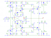
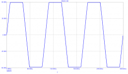
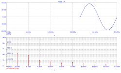
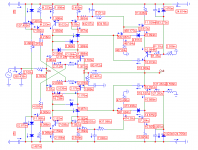
Gentlemen, take this debate as mental exercise, that it is possible to make this schematic(with current mirrors) reliable working with very good results, with some modifications without sticking problem and with fast recovery. It is not cookbook..Schematic and simulation are attached. All diodes 1N4148, NPN-BC546B, PNP-BC556B, VAS output (Q13, Q14) MJE340,
MJE350. Models by NXP and ONsemi. SR is about 100V/us, clean without overshots.
, that it is possible to make this schematic(with current mirrors) reliable working with very good results, with some modifications without sticking problem and with fast recovery. It is not cookbook..Schematic and simulation are attached. All diodes 1N4148, NPN-BC546B, PNP-BC556B, VAS output (Q13, Q14) MJE340,MJE350. Models by NXP and ONsemi. SR is about 100V/us, clean without overshots.
Attachments
Last edited:

Or convergence issues. I'll try other models.
Thanks anyway.
Edit1: It's working now (I overlooked some stupid error: a short ).
).
But the VAS standing current is quite sensitive to temperature and component values.
Your previous circuit performs much better!
Edit2: Hey, one more version. You're keeping me quite busy, don't you?
Thanks anyway.
Edit1: It's working now (I overlooked some stupid error: a short
).But the VAS standing current is quite sensitive to temperature and component values.
Your previous circuit performs much better!
Edit2: Hey, one more version. You're keeping me quite busy, don't you?
Last edited:
1 year ago I build an amplifer bassed in Randy´s amp, my 3rd amp.
- Input cascode with current mirror
- VAS cascode
- pair TIP3055/2955
- Output stage with gain x2
- I use this amp with output inductor + R
Hi Havenwood,
You didn't tell us if your Slone Amp worked? If yours worked I have big ears to how you managed to stay away from VAS Iq problems. The difference in your circuit is the Cascode in the IS stage. Does that solve the VAS stability problems? I wouldn't see how but I can't find any other difference in the schematic.
Did you tweak a lot with components?
Anyhow tell us something more about it please ...
Hi Bonsai, I take the idea from Randy. Cascode input stage with current mirror (Glen use this en K12A amp too).Why do you need a current mirror load on the front end LTP's in a fully blanced design? Its fairly easy, if you use a resistive load, to adjust this value in simulation so that the current in the two LTP transistors is balanced and distortion is nulled.
Ic is not balance in inputstage without Current Mirror (Douglas page 82), they are partially balance.
Why cascode? I read a little about this in PassLab and in this forum.
Add this cost a few cents...
Sound better? I can´t say nothing, my first amplifier was P3A and then SiliconChip 20W. I compare the amplifiers, symmetrical and SC, sound different, but better? I don´t know. I don´t have a reference.
Just when I read (pass) goods feature about casode, I use this. I can´t measure anything.
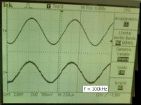
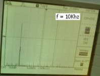
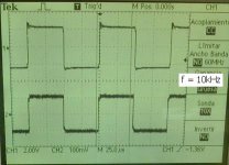
The Amp works fine, very good sound.
Working in Class AB, offset <10mV
=> Some pictures.
Channel 2 (input) from oscilloscope have noise, becouse the ground cable is break, only probe1 have ground (look channel 2, sine + noise or square + noise)
Sorry for my English


Attachments
Hi!Hi Havenwood,
You didn't tell us if your Slone Amp worked? If yours worked I have big ears to how you managed to stay away from VAS Iq problems. The difference in your circuit is the Cascode in the IS stage. Does that solve the VAS stability problems? I wouldn't see how but I can't find any other difference in the schematic.
Did you tweak a lot with components?
Anyhow tell us something more about it please ...
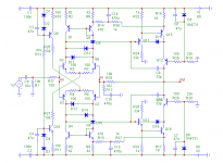
I have no problems with Iq, use Re = 100ohm, and cascode VAS set the transistroe operation point.
Need 2 adjust, Iq and Voffset (no DC servo)
I attach a zip file, with amplifier simulation (PSPice)
Attachments

- Status
- This old topic is closed. If you want to reopen this topic, contact a moderator using the "Report Post" button.
- Home
- Amplifiers
- Solid State
- HEEEELLLPPP : M. Randy Slone Mirror Image Topology Construction - Troubles