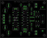
Sapphire board version 12j, eagle files.
I'me wondering what to do about the jumper. Does anyone know a standard part no. for a 3 pin jumper like the ones typically found on computer motherboards?
I'me wondering what to do about the jumper. Does anyone know a standard part no. for a 3 pin jumper like the ones typically found on computer motherboards?
Attachments
you mean a molex connector? They have the part numbers listed in eagle...
Have you tried a greinacher voltage doubler yet for a more HV supply?
I've used it before to feed a tube buffer, I think I got 119V out of a 2x24V PCB mount transformer. All parts sourced from dead PC power supplies (HV caps).
Have you tried a greinacher voltage doubler yet for a more HV supply?
I've used it before to feed a tube buffer, I think I got 119V out of a 2x24V PCB mount transformer. All parts sourced from dead PC power supplies (HV caps).
Last edited:
Kevan,
Try a switch. It might work fine, it might have minor stability issues due to lead inductance inside the feedback loop - give it a shot because it would be fun to have the ability to switch on the fly. Maybe later once you know which you want you can remove the switch and solder a permanent jumper.
Digits,
Not a molex, the smaller square pin header used for, eg, the USB headers on motherboards. By the way the circuit is current rather than voltage limited, so increasing the power supply voltage wont do much...
I've been messing around with my soundcard hooked up to the Sapphire, generating some benchmarks with Rightmark.
I'm afraid it'd not going to tell you anything we didn't know already: there's basically nothing to measure. No significant noise, distortion, or deviation in frequency response compared to the soundcard by itself.
I'm a proponent of using measurements to find and diagnose problems. I'm not much for using measurements to evaluate sound quality. That's what ears are for. The measurements are clean, the Sapphire amp works as designed. The rest is in the realm of subjective opinion.
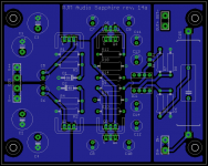
Latest board revision 14a
- feedback loop adjust pads made in-line, with 0.1 pitch, should fit standard part pin strip headers 3M 2300, 929 series.
- all other wirepads are made standard 0.2" spacing to fit standard screw terminals if desired.
- hole spacing for board standoffs changed to match 3.5"x2.5" of current Phonoclone 3 and VSPS300 boards.
- use "restrict" layer to prevent unwanted polygon flow, rather than making strange polygon shapes to avoid the area. (same result, but better design practice)
Relevant files updated at the web page.
Attachments
Finally finished my sapphire. I had planned to fit a LDR volume control but there wasnt enough space in the box. Ended up using a cheap 25k pot from Jaycar for now. I need to get 4 new matched LDR's to work on a smaller board.
I did try a switch for buffer in/out. I used wire from a USB mouse and a small switch. On B1 I had hum and B2 loud oscillation. Removed the switch and found a problem with one channel. Turned out that one of the legs of Q2 wasn't soldered properly.
Still running it in with earbud phones and it does sound promising.
Hope to get a better pot or LDR volume sometime soon. I'm using my phonoclone3 power supply - 80 va tx +2 rectifiers. I plan to run a second cable out of the box instead of building another. Would that be OK Richard?
Kffern
An externally hosted image should be here but it was not working when we last tested it.
I plan to run a second cable out of the box instead of building another. Would that be OK Richard?
I never did try that. From a power point of view there's no problem, but check by running the wires out the open case before drilling any new holes, just to be sure there isn't any increased hum as a result of a group loop introduced by the shared power supply.
Thanks for the photo.
That volume pot looks pretty suspect, but other than that it's all shipshape. Is that a plastic case though? Ew...
/R
Well I am finally able to report back with my conclusions about RJM’s Sapphire. Apart from time and energy, I’ve had a few other problems. Finally made a second power supply with a potted 50VA TX and dual rectifiers. Then received the Valab 20K pot, fitted it and couldn’t close the case! Bumping up against the boards by barely a mm. Swapped it out with the 20K pot from my Pass B1 pre (ebay, gigawork). The Valab seemed better – quieter and more detailed. Then the dog ate my HD650. Luckily just the cable about a cm from the right plug.
Now the Sapphire head to head with my Benchmark DAC (early model).
Pre out (direct and not adjusted so 2.5V I think) from the Benchmark into the Sapphire (ancient Kimber PBJ). Source is an Ipod through an Onkyo ND-S1 digital out. Ipod files are all .wav files. Volume matched as close as I could get.
The Benchmark initially sounds fuller and stronger in the base and the Sapphire a bit leaner and more detailed. After a bit of A/B listening I realised that the Sapphire has a much lower noise floor making fine detail and channel separation quite a bit better than the benchmark. Listening to Amy Winehouse “ I heard love is blind” the brushes are so much better delineated through the Sapphire and seem to hang in the air. Through the Benchmark you can hear them but you just know they are there, with the sapphire they hold the tune beautifully. A bit like listening to an electrostatic after a cone speaker. Basically I thought the HD650s sounded as good as my electrostatics (ER Audio) through the Benchmark but the Sapphire there’s even more detail and stereo separation.
I’m crap at expressing myself even after a large single malt and an evening alone with my hifi.
I strongly recommend the Sapphire especially to those that have built the pnonoclone/VSPS as I have.
Good work and thanks RJM.
Still have to experiment with dual leads from a power supply and maybe if time and funds permit an optivolume. Will get a better case and put some feet on it. I should add that I have not used any “hi-fi” components. Input cap is Axon but apart from that all Jaycar/Altronics budget stuff, plastic box, Cat5 wire etcand op27 opamps. Maybe now I’ll DIY a better case.
I thought someone else was building one? I have ordered a couple of O2 boards so lets see how they stack up or they’ll got to the kids.
kffern
Nice to see the circuit and build worked out well for you rjm ")
I still haven't got around to properly building mine, and even worse the prototype on breadboard has killed my Beyer DT231's due to a loose wire - output went to -V and fried them The usual 120 ohm resistor probably would have prevented the damage.
I still haven't got around to properly building mine, and even worse the prototype on breadboard has killed my Beyer DT231's due to a loose wire - output went to -V and fried them
The usual 120 ohm resistor probably would have prevented the damage.@jaycee
Ideologically I'm in favor of the 120 ohm output series resistance. It gain-levels the output against various headphone loads, and, as you say, serves as over-current protection.
The general consensus however is that headphone amps sound better with it left off. I did an extensive web search, and the same thing was found over and over. So I left it off. Sorry. You are welcome to put it in (increase R14 to 120 ohms) of course, though its a bit late.
@kkfern
(begin rant)
Damn it, use a bigger case! Everyone seems to size cases by looking at the board area. Don't. Minimum internal floor area should be twice the size of the boards. Keep plenty of room front, back, and sides to mount connectors and jacks, and route wire leads.
It would save everyone so much work in the long run.
(end rant)
If you measure the voltage across R12, R13 , the current V/R is the current though the output devices Q5 Q6. I'd appreciate it if you could report that number to me.
Your listening experience is basically the same as mine: the Sapphire's dominant trait is resolution. Everything is clearly presented. A lousy recording, or any fault in the upstream components is made evident, just at it reveals the intricacies and beauty of well recorded music.
It also has tremendous reserves of clean power. You can really crank it (with 200 ohm headphones at least) and there is no confusion or weakening of the soundstage.
Anyhow, I'm not 100% satisfied: the circuit should work with the buffer inside the feedback loop, and the fact that it doesn't seem to implies something isn't working the way I think it works. Then there is the lower-then-designed-for output current, due to thermal issues.
The latter should be resolved with the new board layout, which is complete but not fabricated.
I should place an order for some of the new boards. Those who bought the original version from me will get a v2 board free.
Due to a mix up the hole spacing is not 100% the same as the Phonoclone3 boards, but will stay as a drop in for the v1 sapphire. (I could fix it, and the uploaded versions are correct, but I want to replace my own Sapphire so will use the old spacing for the boards I get made.)
All the info is here,
RJM Audio - Sapphire headphone amplifier
I still have some of the older boards (rev 10) if you want to quickly get something up and running. Email me if interested.
RJM Audio - Sapphire headphone amplifier
I still have some of the older boards (rev 10) if you want to quickly get something up and running. Email me if interested.
I'd just like to formally set out the pricing plan:
I still have one or two rev 10 boards. These are $20 for a set of two, including shipping.
I will get some rev 14 boards fabbed. These will cost $40 for a set of two, including shipping, except for people who bought the rev 10 boards, for whom it will cost only $20 including shipping.
Alternative what of thinking about it: get a set of rev 10 boards free when you buy a set of rev 14 boards: for comparison, practice, a second unit, or just fooling around.
I also have a decent stock of transistors, op amps, sockets, and capacitors for this project.
I should have rev 14 boards ready in 2-3 weeks.
- Status
- This old topic is closed. If you want to reopen this topic, contact a moderator using the "Report Post" button.
- Home
- Amplifiers
- Solid State
- Headphone amplifier drop-in replacement for Phonoclone 3 and VSPS300