I was outside at the time and didn't notice anything, though I was told that building in Kyoto swayed slightly. You could definitely feel it if you were inside. Sendai coastal regions are completely devastated, though thanks to good warning systems many people were able to escape before the waves hit.
You have made a very nice writeup, you should advertise more! (I had not seen this before.)
http://hifisonix.com/wordpress/wp-content/uploads/2010/10/X-Altra-Mini-V2.0.pdf
PS. The ebay case I posted above is the modushop Galaxy (or a clone). Modushop have a full line, and will custom drill the front panel for you for a reasonable additional cost.
http://www.modu.it/galaxy.html
Last edited:
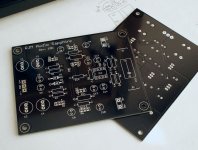
Boards!
Everything looks OK. Not a lot of clearance around the transistors for heatsinks however, I shall have to look into that for later revisions.
This is the first time I've used thermal isolation for the poly fills. Seems to have worked out.
Boards are 100x160 mm, and two are needed for stereo. That's 200x160 in real estate right there, plus another 200x100 for the transformers and diodes and another 200x5 or more for the connections. So about 200x265 is the minimum case dimensions, unless you use an external power supply.
Attachments
Last edited:
I was outside at the time and didn't notice anything, though I was told that building in Kyoto swayed slightly. You could definitely feel it if you were inside. Sendai coastal regions are completely devastated, though thanks to good warning systems many people were able to escape before the waves hit.
You have made a very nice writeup, you should advertise more! (I had not seen this before.)
http://hifisonix.com/wordpress/wp-content/uploads/2010/10/X-Altra-Mini-V2.0.pdf
PS. The ebay case I posted above is the modushop Galaxy (or a clone). Modushop have a full line, and will custom drill the front panel for you for a reasonable additional cost.
modu
Thanks RJM. I had my front and back plates drilled/machined by modushop. BTW their control knobs are absolutely outstanding - solid aluminium and really well made.
I am seriously looked into getting Modushop to do the drilling for me. With a 4 mm faceplate I could manage myself, but 10mm is not something I want to tackle. The trick is which case to use. Did the addition incorrectly last post: case needs to be about 200x310 mm minimum. 230x280 330x230 and 330x280 all possibilities, none stand out as being exactly the right dimensions. I will wait till I have all the parts in hand so I can lay everything out on a table before deciding.
")
Okay, my brain was clearly mush earlier. Let's try this again:
Boards are 80x100mm each, two needed for stereo. Total board area 160x100mm, about the same for the power supply and an additional 160x50mm to clear the front panel components. I'm a proponent of roomy cases, but it looks like 170x250 mm or so should be about right.
Something like this is convenient and should do nicely.
The "DIY" look of perf board, point-to-point, and recycled network router cases is perfectly fine, but in today's age of the internet, ebay and cheaply available Chinese board fabrication and manufacturing capability, a DIYer can easily achieve a near-professional build quality for relatively little extra expense.
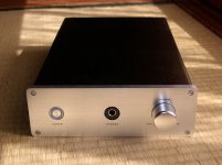
The case arrived, by EMS, just a couple of days after I bought it. All I need add are the RCA jacks, volume attenuator, and a fuse for the included fuse holder. More importantly the only machining I'm left with is 8x 3 mm clearance holes for the boards and 6x 4 mm clearance holes for the transformers and diodes.
As you might guess, I love circuit design, and don't mind building the electronics either, but power tools are just not my thing...
I have everything now but the Mouser parts, which due to a single resistor being out of stock is delayed until April 12th.
As you might guess, I love circuit design, and don't mind building the electronics either, but power tools are just not my thing...
I have everything now but the Mouser parts, which due to a single resistor being out of stock is delayed until April 12th.
Attachments
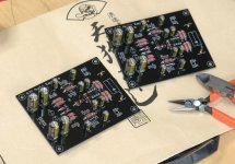
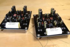
I did some soldering this morning.
This is prototype A. It's set with the buffer outside the current loop, currently with R12,13 at 0 ohms, and omitting C5,6 (the RC filter between the Zener reference and the base of Q1,2).
Soldering was a bit of a pain: even with thermal isolation the pads into the poly fills never seem to want to heat up properly.
Now I'm off to try and match some transistors...
Attachments
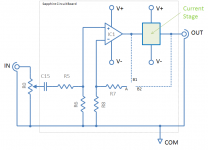
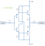
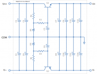
Circuit Schematics
The Zener-based regulator block is lifted from the Pioneer C-21 Preamplifier.
The current stage is a descrete version of the LH0002 IC.
The voltage stage is a generic noninverting op amp amplifier, with a couple of nods to the Bryston BP4.
The Zener-based regulator block is lifted from the Pioneer C-21 Preamplifier.
The current stage is a descrete version of the LH0002 IC.
The voltage stage is a generic noninverting op amp amplifier, with a couple of nods to the Bryston BP4.
Attachments
Finished soldering the boards. A few things cropped up while putting everything together, and the BOM has been revised accordingly. Next step it to power things up on the benchtop and see if they can pass a signal.
Attachments
thanks for sharing. looks interesting ...
just curious - any reason you did not consider/use any of the currently available monolithic diamond buffer design-based integrated circuits like the LME496000, BUF-634, LMH6321, HA-5033, etc.?
btw, i saw your comment regarding the benefit of equally biasing the 4 gain devices.
thx,
mlloyd1
just curious - any reason you did not consider/use any of the currently available monolithic diamond buffer design-based integrated circuits like the LME496000, BUF-634, LMH6321, HA-5033, etc.?
btw, i saw your comment regarding the benefit of equally biasing the 4 gain devices.
thx,
mlloyd1
I did consider most of these.
Lack of availability, lack of availability in through-hole packages, limited ability to set the bias since the emitter resistors are baked in, inability to individually match transistors...
Since I'm really not interested in minimizing board area, and given the extreme simplicity of these circuits, there really is no excuse not to just build it discrete.
By the way I forgot to mention earlier that my attempts to match transistors ended in abject failure. The current gains are so sensitive to substrate temperature that minute variations in the ambient environment swamp whatever manufacturing variations might exist. I gave up and just used whatever ones spilled out first from the bag!
I connected one channel to a power supply and made some DC measurements.
Games and theory are all well and good, but there is no substitute for direct experiments.
So, there are a number of problems, so many that I am going to have to retreat and regroup in order to think of about how to proceed.
The board powered up and did not explode. All DC measurements are as expected, i.e. there are no errors in the circuit, layout, or my soldering and connections.
Problem 1. My 62060 Amveco toroid turned out to be a 62062, i.e. 12 VAC secondaries rather than 7 VAC. Oops. Buy more transformers, replace components on the board, or stuff another board. Since the circuit is working, however, I propose to do as much testing as I can on it as-is before proceeding.
Problem 2. Op amp stage is borderline unstable, runs 60 mV hum on the output with the inputs open, much reduced if the inputs are shorted. Probably solved by a capacitor across R7, with have to look at it in detail later.
Problem 3. Voltage drop across R3,4 is 0.3 V, which drops the V+ down to about 4.7 V for a 5.6V Zener. Starting to think this is not ideal since op amps like the OPA27 don't like to have their output voltage much closer than 2-3 V from the voltage rails. R3,4 should be reduced slightly, and higher transformer secondaries and higher V+ a good idea. Rather than having 6 and 12 VAC versions, 9 VAC seems optimal.
Problem 4. The value of R12,13 ... 1 Ohm kills the output current, 0 Ohms probably makes the circuit thermally unstable. Somewhere there is an ideal value but it is going to take some trial and error, and I don't even have testing method in mind.
Problem 5. This isn't actually a problem, but running the prototype at much higher supply voltages than intended meant that Q1 and Q2 dissipated about 0.8 W of heat, but I discovered that the packages only get very warm, rather than burning hot. 0.4 W is perfectly OK, so it makes sense to raise the bias currents a little to take advantage of this. i.e. I was being overly conservative in my power budget.
So while it's not quite back to the drawing board there are a number of steps to go through now, one at a time, before I even get to the stage of being able to give it a listen.
Last edited:
Headphones typically run between 16 and 300 ohms, with most people probably owning 16 ohm earbuds. Low impedance headphone only need a little voltage (volume level) to play very loudly, while high impedance headphones need a lot. The difference is about a factor of 5-6 (about 10 dB).
One nice way of dealing with this is to add a small resistance (47-68 ohms) in series with the output load, and set the op amp voltage gain to 10x (20 dB). This will naturally attenuate the output voltage as a function of load impedance, such that the volume position at constant loudness becomes independent of headphone impedance. The penalty is reduced efficiency and a high output impedance.
The alternatives are either to design a headphone amplifier for a specific load (I've build a couple which were optimized for my 300 ohm HD600's) or to simply split the difference and go with about 15 dB fixed gain and no series resistance.
Last edited:
- Status
- This old topic is closed. If you want to reopen this topic, contact a moderator using the "Report Post" button.
- Home
- Amplifiers
- Solid State
- Headphone amplifier drop-in replacement for Phonoclone 3 and VSPS300