Is that all you have to say?
ouch!!
hehe,
very interested to read further and implement this design myself
HEC-TMC
Hi Bob,
Till now, about 17 years after I reinvented TMC, in all that time I've also never thought of this.")
Well, just as clever (or obvious!) as TMC in a front-end.
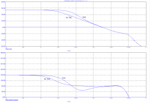
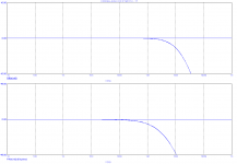
As you know, there ain't no free lunch, though looking at the graphs below, I don't think stability isn't much impaired. At ULFG, 3MHz, the PM of the FB loop is only a few degrees lower (1st pic.). The closed loop response (of the OPS, thus not the whole amp) shows hardly any difference (2nd pic.)
THD20k improvement is about 10dB.
Sure, using 3 pairs will also reduce distortion considerably. Nonetheless you can do both for even higher performance.
I'm planning to use even four pairs, though running at 150mA idle or also 600mA in total. So we are almost on the same track.
>optimized source resistors
Source resistors or do you mean gate resistors or perhaps both optimized?
As you know, I prefer different gate resistors for the P-channel and N-channel devices, and I'm not the only one. Please see this application note, page 10.
Cheers,
E.
Hi Edmond,
No, I've never thought of this.
Hi Bob,
Till now, about 17 years after I reinvented TMC, in all that time I've also never thought of this.
Looks like a clever idea!
Well, just as clever (or obvious!) as TMC in a front-end.
I wonder how stable it would be in the real world.
As you know, there ain't no free lunch, though looking at the graphs below, I don't think stability isn't much impaired. At ULFG, 3MHz, the PM of the FB loop is only a few degrees lower (1st pic.). The closed loop response (of the OPS, thus not the whole amp) shows hardly any difference (2nd pic.)
THD20k improvement is about 10dB.
BTW, my original MOSFET power amplifier with EC used only one pair of MOSFETs with only 150mA of bias and no source resistors for distortion optimization (as described in Chapter 11 of my book). If we go to 3 pair each biased at 200mA and with optimized source resistors, we can probably do a lot better than my original amp.
Sure, using 3 pairs will also reduce distortion considerably. Nonetheless you can do both for even higher performance.
Of course, it will run a little warm, but will also have a very generous class A region extending to output current of 1.2A. With +/- 50V rails, this amp will dissipate about 60 watts in the output stage.
Cheers,
Bob
I'm planning to use even four pairs, though running at 150mA idle or also 600mA in total. So we are almost on the same track.
>optimized source resistors
Source resistors or do you mean gate resistors or perhaps both optimized?
As you know, I prefer different gate resistors for the P-channel and N-channel devices, and I'm not the only one. Please see this application note, page 10.
Cheers,
E.
Attachments
Thank you. I didn't think before I posted.What you see there is the local loop gain of the Miller compensation
What I see in Fig. 6 is actually the loop that includes the local Miller compensation via C16/C17 plus the feedback via the TMC resistor R33 (To use Fig. 6 identifiers because the thumbnail is a bit cropped))
I am curious about the loop response of just the local Miller compensation.
That would be between the junction of C22 and C23 and R28 on Fig. 12.
Could you show the loop gain for that?
I think I have invented ( or independently reinvented, probably) a form of nested TMC and I would like to compare my results with your SuperTIS.
My idea to combine them was to eliminate any possibility of capacitor mismatch. But I checked the RC time constant and you are correct that it would be a problem. Hmm.The intention here is that the Miller caps (C19 & C20, see pic below) are directly connected to the output of the TIS buffers, i.e. to the emitters of Q21 respectively Q22.
Best wishes
David
BTW. My Frau informs me that a Schweitzer waste of effort is "for the cat" - Not for any particular part of the cat
Thank you. I didn't think before I posted.
What I see in Fig. 6 is actually the loop that includes the local Miller compensation via C16/C17 plus the feedback via the TMC resistor R33 (To use Fig. 6 identifiers because the thumbnail is a bit cropped))
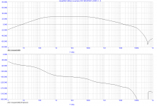
I am curious about the loop response of just the local Miller compensation.
That would be between the junction of C22 and C23 and R28 on Fig. 12.
Could you show the loop gain for that?
Of course, see blow. As you see, the max. gain is a bit limited. This is one of the reasons I reverted to the original compensation according to fig.6, though with slightly larger capacitors. The other reason is that this scheme performs clearly better (THD wise). I thought that the simpler compensation was just as good, but it appeared that I was fooled by one of the simulations. BTW, I've dubbed the 2nd order shunt compensation (C12...C15, R26...R28) Transitional Shunt Compensation or TSC.
I think I have invented ( or independently reinvented, probably) a form of nested TMC and I would like to compare my results with your SuperTIS.
You made me curious.
My idea to combine them was to eliminate any possibility of capacitor mismatch. But I checked the RC time constant and you are correct that it would be a problem. Hmm.
Never mind. A design as complicated and unconventional as this one, can easily lead to misinterpretation.
Best wishes
David
BTW. My Frau informs me that a Schweitzer waste of effort is "for the cat" - Not for any particular part of the cat
Your 'Frau' is right. There are a dozen variants on this saying, to name a few (translated):
'for the cat his ăss'
'for the cat his raisin'
'for the cat his left eye'
'for the cat his tail'
'for the cat his balls'
'for the cat his violin'
'for the cat his whiskers'
But 'voor de kat zijn kut' is the most common because of the alliteration.
Sorry guys for getting slightly off-topic.
Cheers,
E.
Attachments
Last edited:
matched duals
Hey David,
What about 2SA1349 and 2SC3381 for the IPS and current mirrors?
Perhaps not the lowest noise you can get, but at least monolithic, thus matched.
JohanB offers them for affordable prices.
Cheers,
E.
PS: and higher beta than THAT300/320/340
Hey David,
What about 2SA1349 and 2SC3381 for the IPS and current mirrors?
Perhaps not the lowest noise you can get, but at least monolithic, thus matched.
JohanB offers them for affordable prices.
Cheers,
E.
PS: and higher beta than THAT300/320/340
Last edited:
Hi Harry,
Thanks for your concerns.
As it is a DIY project, I don't care much about obsolete parts, that is, as long as I can get them now. The Toshiba MOSFETs I'm planning to use are also obsolete, yet I could buy them. In case they are sold out totally, one can always replace them by other MOSFETs.
As for the SSM's, I did consider to use them (and asked for a quote), but they are far more expensive and the beta of the PNP version is not impressive. The same applies to the THAT320.
So I opted for the 2SA1349 and 2SC3381. Moreover, one can always replace them by hand matched discretes, as the PCB foot-print is compatible with TO-92 BCE trannies.
>genuine parts
Regarding Johan, I've no reason to distrust him.
BTW, in the past I bought already above parts, that is, genuine parts.
So I can always compare them with the new ones, starting first with an careful optical inspection. Fakes look almost always (slightly) different.
Cheers,
E.
Last edited:
The 2SA1349 and 2SC3381 ARE nice parts for Stuart's application.
And, just to quell any concern, ...
the parts I've gotten from Johan were good; I've compared to other NOS and was pleased.
They are GR grade (as opposed to the higher beta BL grade) if that matters to anyone.
mlloyd1
And, just to quell any concern, ...
the parts I've gotten from Johan were good; I've compared to other NOS and was pleased.
They are GR grade (as opposed to the higher beta BL grade) if that matters to anyone.
mlloyd1
Hey David,
What about 2SA1349 and 2SC3381 for the IPS and current mirrors?
Perhaps not the lowest noise you can get, but at least monolithic, thus matched.
JohanB offers them for affordable prices.
Cheers,
E.
PS: and higher beta than THAT300/320/340
Edmond, you can look here http://www.linearsystems.com/datasheets/LS310-3.pdf and here http://www.linearsystems.com/datasheets/LS350-2.pdf
Damir
LS
Hi Damir.
I know of them. At first sight nice chips: tight Vbe matching an high beta. But aren't they a bit fragile: Icmax= 10mA. Also, what about noise (not specified), where to get them and how expensive they are? Questions, questions, questions.
AFAIK, this company isn't happy with small orders, let alone requests for samples.
For a one-time project, I'm quite satisfied with the Toshiba BJT duals.
Cheers,
E.
BTW, I've dubbed the 2nd order shunt compensation (C12...C15, R26...R28) Transitional Shunt Compensation or TSC.
That's interesting, because I came up with the same type of compensation scheme and even thought of the exact same name. I used it on a poweramp that I built and tested. It can confer the benefits of TMC without Miller drawbacks such as lowered PSRR and conduction of output stage switching pulses.
EDIT: And extra first-order input stage loading. So far I like it better than TMC, MC or Two-pole, but I don't know nearly as much as you.
Last edited:
TSC
Hi Kris
I only heard it from hearsay. Apparently, I was misinformed.
Hi Keane,
That's funny. Same trick AND same name. Clearly same minds as well.
Whether it's better than other compensation methods depends heavily on circuit details. Generally, I'm not in favor of shunt compensation, as it drains 'valuable' signal current to ground. Instead, I prefer to put the 'wasted' current in good use by feeding it back to some suitable input (Miller, MIC, etc.). But as always, there are exceptions.
Anyhow, herewith the acronym TSC ® has officially been registered.
Cheers,
E.
Linear Systems supplied me with samples with a smile and no hitches, about a year ago, paid for express shipping and seemed very friendly. lsk389 I think.
Hi Kris
I only heard it from hearsay. Apparently, I was misinformed.
That's interesting, because I came up with the same type of compensation scheme and even thought of the exact same name. I used it on a poweramp that I built and tested. It can confer the benefits of TMC without Miller drawbacks such as lowered PSRR and conduction of output stage switching pulses.
EDIT: And extra first-order input stage loading. So far I like it better than TMC, MC or Two-pole, but I don't know nearly as much as you.
Hi Keane,
That's funny. Same trick AND same name. Clearly same minds as well.
Whether it's better than other compensation methods depends heavily on circuit details. Generally, I'm not in favor of shunt compensation, as it drains 'valuable' signal current to ground. Instead, I prefer to put the 'wasted' current in good use by feeding it back to some suitable input (Miller, MIC, etc.). But as always, there are exceptions.
Anyhow, herewith the acronym TSC ® has officially been registered.
Cheers,
E.
Last edited:
Thank you for the loop data in that post. Hope this helps satisfy your curiosity.You made me curious.
Generally, I'm not in favor of shunt compensation, as it drains 'valuable' signal current to ground. Instead, I prefer to put the 'wasted' current in good use by feeding it back to some suitable input (Miller, MIC, etc.)...
This is also my idea behind the nested TMC that you were curious about.
In some ways similar the Ed Cherry's NDFL in reverse. It nests around the IPS and therefore has the improved slew rate of Miller input inclusive compensation. It also appears to have another bonus. Somewhat obscured be Cherry's maths are a few idealizations that are fairly dubious. This scheme should be better with respect to inevitable non idealities. But of course the maths is harder when less idealized so I haven't finished yet.
Basically, rather than shunt compensation you return the 'wasted' current to the input. When I first asked you about this you replied that it decreased stability.
So the trick is to use nested TMC to decrease the return ratio sufficiently fast to ensure stability.
Like your TMC error correction, obvious once you think of it - but no one came up with that for decades!
More when I have done a few tests.
Best wishes
David
BTW. In the transistor quiescent current arms race. I plan to use 6 pairs
Last edited:
Hi Keane,
That's funny. Same trick AND same name. Clearly same minds as well.
I'm flattered, as your personality stands out here, in a good way so far as I've seen. You appear so calm and rational. For me this is difficult, but it is a work in progress.
You are right about circuit details. However with Miller compensation, the current is also wasted, as most of the current going through the miller cap is drained away through the VAS. What current isn't wasted is not necessarily helpful because it has the reverse polarity of the VAS and bends the gain over backwards. This unecessary phase can be troublesome, especially with second-order input impedance strangeness of a double or triple EF. In my builds I found shunt compensation was less likely to cause strange, difficult to trace oscillation problems. TSC gives the benefit of second-order input stage loading without excessive VAS loading. It can also improve distortion with output stages that have low current distortion but high voltage distortion as is typical of buffers.
Of course I like it though, since it's sort of my pet. The lowered input and VAS loading is helpful for tolerance of ultrasonic noise, and PSRR is greater.
I have not explored various schemes in-depth as much as this post may suggest, so I may be sucking on my toes. I will throw together a TIS simulation and check out various things. Since I don't know much math, it may be difficult for me to achieve the same quality of work, but so far that hasn't stopped me entirely.
An example of how I imagine TSC being employed is on Symasym, splitting the 330pF caps after the output stage. This amp is a perfect example of shunt compensation.
An example of how I imagine TSC being employed is on Symasym, splitting the 330pF caps after the output stage. This amp is a perfect example of shunt compensation.
I meant after the VAS, not the output stage. Symasym schematic:
Hi Keane,
If you don't mind, above circuit (in its present form) hurts my eyes:
What are the two 47k resistors to gnd doing there? The only thing I can think of is increasing the distortion at LF. Has JC recommend this?
Then the 100pF cap. In that position it provides hardly any compensation. It only loads the IPS asymmetrically and decreases the PSRR.
And finally the two 330pF caps. Indeed, they are very good candidates for TSC. Do you already have some sim results?
Cheers,
E.
Hey Edmond, I am a fresh new student to electronic engineering. Can you quickly, tell me how your master piece would stand sonically in between a high-end 6dj8 mic pre (or any valve pre) compared to a microphone pre as GML makes, in all there transparent glory. I cannot wait until I can look at a schematic and be able to understand, and even predict how the circuit would sound.. So bare with me and keep it simple, for I don't hope for you to waste much time, other than to help aid my idea of how such a symmetric design might sound.. I am sure it carries it's own sonic footprint, and I have never heard, let alone seen a design where its symmetric as yours.
It is very interesting to say the least, and intrigues me more and more at the idea of simulating it... I'd even want to build it myself, but I don't know the rules for-say, if that would be morally wrong,, or stealing.. i don't know.. I just am so damn interested, and so young, i needed to speak out and say something.
Hope to to bother you too badly : )
- Status
- This old topic is closed. If you want to reopen this topic, contact a moderator using the "Report Post" button.
- Home
- Amplifiers
- Solid State
- Has anyone seen this front-end before?