You can also use non isolated drive on the mosfets as well. If you switch the speaker ground return line, the drive is very simple: Audio Amplifier Design and Circuits | hifisonix.com a topics down from the top of the page.
Hi Andrew,
That is a very neat and clever solution.
>distortion [..] and the figure is less than 1ppm
Do you know how much 'less'?
Cheers,
E.
Hello Edmond.
Only in simulation from my side. However, there was a guy on the forum that ran one of their SSLR's through an AP and the distortion was basically buried in the noise floor ie 1ppm. Sorry, I cannot remember who it was. However, since you are shooting for <100ppb, you can always put the SSLR inside the feedback loop. Of course, then you will need to switch the speaker hot wire, and not the ground return. Bob Cordell showed a solution in his book on how to insert a conventional loudspeaker relay inside the feedback loop.
Of course, I can also imagine a solution in the ground return line where you use an opamp to measure the volt drop across th relay and then modulate the gate drive to keep the voltage drop constant. However, I am ok with the levels as discussed in my document.
Looking forward to seeing pictures of your amp btw!
I said a GOOD electrolytic.
Cheers,
Bob
LOL!
And watch out for those ceramics too btw! The only good ceramic is one that not on your amp or preamp board.
Hi Steven,
Thanks for providing the schematic. Indeed, a thermally isolated servo is a very clever and original solution. I've never seen this before.
BUT.... it has the same drawback as a conventional servo: over twenty additional components. It is again a trade-off between complexity and performance; that's precisely my dilemma.
BTW, maybe using optocouplers for isolation also provide a viable solution.
>Chocoholic once posted a circuit for a MOSFET relay:
Thx for the hint!
Cheers,
E.
Hi Edmond,
Am I correct in assuming that you are talking about a conventional power amplifier DC servo?
The one I prefer, and described in my book, uses an inverting integrator and an inverter, using a single JFET dual op amp and an integrator capacitor. It is completed with 2 protection diodes and 4 resistors, for a total count of 8 small cheap components.
If I add an optional additional RC noise filter after the integrator, it adds one small capacitor and maybe one resistor.
Where do you get 20 components?
Cheers,
Bob
And watch out for those ceramics too btw! The only good ceramic is one that not on your amp or preamp board.
no reason for this level of ignorance today - NP0/C0G ceramics are quite good on all specs, even DA which some claim is the explainer of "audio quality"
higher K X7R may not be the best for signal apps but the higher C density can be useful in PS bypass, local C, low inductance are needed for today’s faster op amps, some suitable for audio reaching 50 MHz GBW
DBT test of audio circuits with film vs X7R bypass have gone the "wrong" way - the ceramic bypassed boards rated as "sounding better" as long as the evaluation was blind
Last edited:
Yes, no need for this level of ignorance. Agree hat NPO/COG are very good. Beyond that, they are mostly problematic. Temperature dependancy and Voltage dependancy are two hings that concern me most.
If you are talking about output filter caps in an SMPS, then they are ok. Bottom line is for decoupling and time constant setting, there are better solutions (NPO/COG the exception).
If you are talking about output filter caps in an SMPS, then they are ok. Bottom line is for decoupling and time constant setting, there are better solutions (NPO/COG the exception).
22
>Where do you get 20 components?
Hi Bod,
On page 165 of your book I really do see 10 components:
U1, C3, R4, R8, R7, R6, C2, R5, D1, D2.
Then we have the PSU:
2 Regulator ICs (+ and -15V)
2 Resistors and 2 Zeners to lower Vin for the regulators.
4 Electrolytic caps, put at both sides of the regulators.
2 Ceramic caps to by-pass Vdd and Vss of the op-amp.
In total 12 components and together with the servo that makes 22.
Cheers,
E.
[...]
DBT test of audio circuits with film vs X7R bypass have gone the "wrong" way - the ceramic bypassed boards rated as "sounding better" as long as the evaluation was blind
I'm not surprised at all.
Cheers,
E.
Take a look at the temp coefficient and even more importantly the voltage coefficient
Basics of Ceramic Chip Capacitors
As to the sound tests and ceramic sounding better or worse, well, 0.5% distortion amps regularly score higher in golden ears reviews, so I am really not going comment on the impact on sound quality.
My concerns are really more around the use of ceramics in other areas of amplifier circuits. During testing on my e-amp, the ceramic snubber caps that I originally used sang at the test frequency when the output got to above 30V pk. In a separate issue, I used MLCC devices to decouple the cascode bases and also had problems. Use poly caps or silver mica and you have none of these issues.
Last edited:
>Where do you get 20 components?
Hi Bod,
On page 165 of your book I really do see 10 components:
U1, C3, R4, R8, R7, R6, C2, R5, D1, D2.
Then we have the PSU:
2 Regulator ICs (+ and -15V)
2 Resistors and 2 Zeners to lower Vin for the regulators.
4 Electrolytic caps, put at both sides of the regulators.
2 Ceramic caps to by-pass Vdd and Vss of the op-amp.
In total 12 components and together with the servo that makes 22.
Cheers,
E.
Thanks for explaining this Edmond. Virtually all of my amps have a clean +/-15V supply anyway. I would not charge the use of a DC servo with all of the ancillary parts you mentioned to obtain +/- supplies to operate the DC servo op amps.
Cheers,
Bob
no reason for this level of ignorance today - NP0/C0G ceramics are quite good on all specs, even DA which some claim is the explainer of "audio quality"
higher K X7R may not be the best for signal apps but the higher C density can be useful in PS bypass, local C, low inductance are needed for today’s faster op amps, some suitable for audio reaching 50 MHz GBW
DBT test of audio circuits with film vs X7R bypass have gone the "wrong" way - the ceramic bypassed boards rated as "sounding better" as long as the evaluation was blind
I agree. I see no problem using X7R ceramics for power supply bypass applications.
BTW, in some circuits, some designers may suffer high-frequency parasitic oscillations, sometimes at a low level, due to the very low ESR and high Q of ceramic capacitors as compared to some other capacitors. The low-ESR of the ceramics can form resonant circuits with stray inductances or enhance the ability for parasitic oscillations to occur. I learned this the hard way 40 years ago at Bell Labs. I often make sure that ceramic power supply bypass caps are accompanied by an aluminum electrolytic, whose ESR damps any resonances.
Cheers,
Bob
Hi Bob,
The trouble is that my amp has NOT a clean +/-15V supply anyway. This should explain my reluctance to a servo. OTOH, if I incorporate a +/-15V PSU*, I may put it for good use for other things as well, for example a balanced line receiver.
* 12 extra components for a discrete implementation.
Cheers,
E.
Hi , Edmond
A +-15V PSU using a separate transformer is indeed mandatory
to supply DC output protection circuitry since it would be hasardous
to feed this part using the main PSU of an amp that just failed.....
Personnaly i did it this way to supply DC and temperature protections.
A +-15V PSU using a separate transformer is indeed mandatory
to supply DC output protection circuitry since it would be hasardous
to feed this part using the main PSU of an amp that just failed.....
Personnaly i did it this way to supply DC and temperature protections.
HEC-TMC
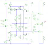
By the way Bob, did you consider the possibility to apply TMC to the frequency compensation of your HEC-OPS as well? Combined with a low distortion front-end, also equipped with TMC, my sims indicate that you can break the 1ppm barrier with this arrangement.
See below how I've done it. Also notice that an extra EF stage is needed (Q24 & Q25, to unload the front-end) and R33 & R38 are increased (i.e. optimized) from 680 to 725 ohms. As for the latter, now it pays off to do this, as the bandwidth of the HEC FB loop has been increased, (around 250kHz, while the ULGF has been kept unchanged: 3MHz).
Cheers,
E
Attachments
Last edited:
By the way Bob, did you consider the possibility to apply TMC to the frequency compensation of your HEC-OPS as well? Combined with a low distortion front-end, also equipped with TMC, my sims indicate that you can break the 1ppm barrier with this arrangement.
See below how I've done it. Also notice that an extra EF stage is needed (Q24 & Q25, to unload the front-end) and R33 & R38 are increased (i.e. optimized) from 680 to 725 ohms. As for the latter, now it pays off to do this, as the bandwidth of the HEC FB loop has been increased, (around 250kHz, while the ULGF has been kept unchanged: 3MHz).
Cheers,
E
Hi Edmond,
No, I've never thought of this. Looks like a clever idea!
I wonder how stable it would be in the real world.
BTW, my original MOSFET power amplifier with EC used only one pair of MOSFETs with only 150mA of bias and no source resistors for distortion optimization (as described in Chapter 11 of my book). If we go to 3 pair each biased at 200mA and with optimized source resistors, we can probably do a lot better than my original amp.
Of course, it will run a little warm, but will also have a very generous class A region extending to output current of 1.2A. With +/- 50V rails, this amp will dissipate about 60 watts in the output stage.
Cheers,
Bob
My aim is trying to build an amp that can withstand any kind of critic.
Impossible! Someone will complain that it is not as simple as a one transistor circuit. Someone will complain that it uses transistors anyway. Someone will complain that the servo roll-off at 1 Hz is not only audible but sounds worse than a tin can telephone. Someone will complain that the capacitors are the incorrect colour. etc. etc. blah blah.
Your experience is based on real data, just build it the way you think is optimum.
Best wishes
David
Last edited:
- Status
- This old topic is closed. If you want to reopen this topic, contact a moderator using the "Report Post" button.
- Home
- Amplifiers
- Solid State
- Has anyone seen this front-end before?