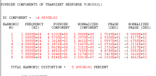
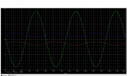
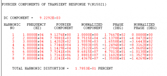
Got the sim to converge at higher resolution by replacing the BSS159 current sources with ideal sources of the same value. Distortion at 8V peak output is ~0.5%, mostly 2nd harmonic with a touch of 3rd. Higher order products decline steeply as function of harmonic order. So, overall gain is about 16x (24dB) - not too hard to drive.
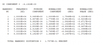
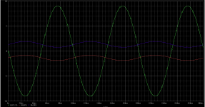
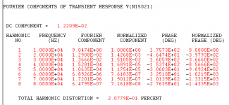
Distortion for 1W RMS output is 0.178%, mostly 2nd, with 3rd down 20dB and 5th & 7th down almost 60 dB.
Distortion for 1W RMS output is 0.178%, mostly 2nd, with 3rd down 20dB and 5th & 7th down almost 60 dB.
Last edited:

I noticed some mistakes on the silk scrren that will get cleared up on the next board run.With the top side ground plane, the top silk screen is hard to read, so I didn't catch a couple of boo-boos. Fortunately, the traces are hunky-dory. The original version of Half Nelson was done on our CNC board milling rig at work, so there weas no silk screen on the previous version anyway.
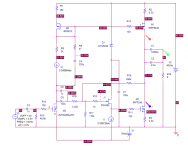
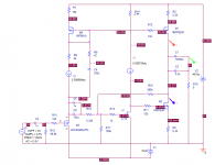
I was farting around in PSpice with a variant of the Half Nelson (actually a bit closer to my original conception), trying to get better matching between the output current of the top and bottom halves. , The farting around was somewhat fruitful, and resulted in substantially lower THD for the same input excitation level (0.5V), as well as better top-bottom current matching. I think I'll be doing similar piddling around for the variant that currently has boards in process, which uses a p-channel buffer rather than an N-channel buffer in front of the lower output device. The biasing is a little different between the two variants, but I would expect similar THD results from the tweaking.
Attachments
")
It looks like DHL may have delivered my boards to the wrong location. They may show up later, or maybe I'm SOL. It's too bad, as this was an amp that I though I could bring up relatively quickly.
Ahh that sucks! Here's hoping the boards show up!
I've been considering my strategy for selecting devices for this project. The input ZVP3306A mosfet can be from random selection, as it is capacitively coupled to the next stage.The J175 will be selected for consistency in settings for output centering and bias. Both output devices will be matched for consistency in bias settings. In the original incarnation of this project, I don't think any device was selected - it's hard to remember exactly, as this all went down all the way back in 2007.
Last edited:

- Home
- Amplifiers
- Pass Labs
- Half-Nelson Amp