
I want my next pass on the Half-Nelson to be both eccentric and pretty (I only got one of the two the first time around - guess which one?), so I'm looking at some interesting combinations of Corian and anodized aluminum. I have a bunch of Corian scraps (sink cutouts!) on the way so I can get used to the look and feel of the material, and perhaps also to use it as front panel material on another project. If anyone on this list has had experience with cutting/machining/routing/gluing/polishing Corian, chime in with suggestions. My eyes and ears are open wide. Pictures wouldn't hurt, either.
I've gone as far as to lay out the next version of the Half-Nelson. This one will use the Semisouth SiC depletion mode fet in place of the IRFP240. I've calculated a preliminary bias point and stuffed the board accordingly. I figure I'll start with a 40V Vcc and somewhere between 1.2-1.5A output bias current. This will be partially determined by my choice of heat sink, as we're talking about ~100-120W dissipation, which is a tall order, even for a heat sink augmented with a low speed fan. I don't want the heat sink to be too hideously huge.
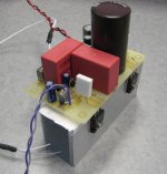
The heat sink on the current version of the Half-Nelson (picture at the beginning of the thread) eventually gets to about 55C with a little over 50W dissipation. With a little 12V fan sitting on top (dialed down to 8V), the heat sink barely gets warm. I found it a bit amusing that during the last Burning Amp, when this amp was auditioned, casual passers-by (almost to a man) couldn't resist a laying on of the hands to see how hot the heat sink was getting - kind of like a benediction...
I picked up a 12V, 120mm fan with low current draw a couple of days ago that appears intended to run at slow speed, even with full input voltage. If I can run it at 6-7V, this may be just the ticket for cooling a modest-sized heat sink. I plan to mill a recess in the heat sink fins so that the fan can be flush mounted.
I want to keep the overall "works out in the open" look of the present Half-Nelson, but with nicer materials and implementation. As I mentioned before, I'm considering pairing up anodized aluminum with Corian. There's some nice blue marbled Corian that would look gorgeous with gold Anodized aluminum. Black and gold would also look rather swank. Once I settle on a heat sink, I'll be talking to a local plating house about anodizing, and looking at some color samples. I want a gold anodize, but not too blatantly yellow. One of the "bronze" options might be a better choice. If I can get away with it, I may pay the extra $20 or so and have the parts hard-coated.
I've also been rummaging around on Ebay, and there's a whole load of reasonably priced cutting boards made with lovely woods that would be an interesting option for a base plate. First thing, though, is to get the breadboard of the next revision going with an improvised heat sink and bench supplies, in order to dial in a bias point.
I've also been rummaging around on Ebay, and there's a whole load of reasonably priced cutting boards made with lovely woods that would be an interesting option for a base plate. First thing, though, is to get the breadboard of the next revision going with an improvised heat sink and bench supplies, in order to dial in a bias point.
Here's a pic of the breadboard for one amp channel for the newest revision Half Nelson that I'll be using for initial tests. Since this amp (just one channel) will be blowing about 50W when set up properly, there will be a fan blowing full tilt on the heat sink. The real deal will be situated on a much larger heat sink (probably with a slow fan), but that's for later. The circuit uses a Semisouth 085 depletion mode fet and an IRFP9240 in the output stage. A schematic will follow when I'm satisfied with test results.
Attachments
I was interested enough to try simulating your earlier posted circuit but couldn't get an amplifier out of it after swapping a couple parts for what I had models of. I think I found that either its a pretty finicky circuit or that I don't understand it very well. Looking forward to the next schematic.
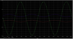
It's not a particularly finicky circuit, either in simulation or in practice. Take a cue from the schematic in post #7 (which actually works fine in simulation - it was the one used to generate the subsequent simulation data) and use a current souce in place of the LM317 or Supertex depletion mode mosfet used in the actual circuit, and it should simulate just fine. That's probably what's tripping you up. I've been setting whatever current source I've been using to 10mA, so that's the value you should use in simulation.
I've been using PSpice for my simulations, which has models for all the rest of the semiconductors, including the Zetex ZVP3306 mosfets I'm using for the input buffer and output stage biasing. Those are relatively important as well. If you use a larger device (say, for example, the IRF9510), the bias point for the output stage will be different. It can be made to work, but you'll have to change the biasing resistors around.
I've been using PSpice for my simulations, which has models for all the rest of the semiconductors, including the Zetex ZVP3306 mosfets I'm using for the input buffer and output stage biasing. Those are relatively important as well. If you use a larger device (say, for example, the IRF9510), the bias point for the output stage will be different. It can be made to work, but you'll have to change the biasing resistors around.
I had some success setting up my breadboard with bench supplies and tweaking up the bias resistors. I'll post a new circuit when I'm sure that the amp can actually deliver a signal. However, this will not be of much help for those who cannot obtain the Semisouth 085 depletion mode device. For those folks I recommend the original Half-Nelson circuit that still sounds pretty nice with more easily obtainable output devices. I can probably provide some guidance for setting up the amp with a higher power supply voltage and bias current for more power. For details like actually building and heat-sinking the thing, you'll be on your own.
The breadboard amp is settling in on the bench as I write this. It's running right now at about 40V Vcc and about 1.3-1.4A bias current - stable so far. An 80mm 12V fan a few inches away from the heat sink is enough to keep the heat sink just warm. At home. I'm using a 120mm, 12V, 0.14A fan to cool the original Half-Nelson amp in my living room. Run at 6V, the fan is barely audible, and keeps the heat sink almost stone cold just sitting on top of the heat sink with no sort of cowl or air guide whatsoever. I think the 120mm fan will adequately cool whatever heat sink I decide to use with the second version of this amp, even though it will be dissipating about twice the power of the original.
Next up is looking at how the amp comes up when just slammed on. This is a concern, as there is now both a positive and negative supply (gotta control that depletion mode FET), so proper power supply sequencing is important. Once I figure that out, then it's testing under load.
I'll post the circuit I have so far when I get back to my home computer.
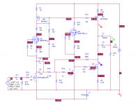
Here's the schematic I'm working with - very similar to the original Half Nelson, but with a negative supply added so that I can properly bias the Semisouth depletion mode fet. I also took the opportunity to return the drain of the input p-channel mosfet to the negative supply to give it some more voltage headroom. A current source has been added to the jfet driving the output fet gate, more or less because I could. The pot it used to adjust the centering of the output top 1/2 Vcc for maximum symmetric operating swing.
The amp works (it amplifies!). However, I'd like the gain to be a bit higher (it's around 11X at present). Also, I'm not getting as much undistorted output swing as I'd like. Finally there's some well damped overshoot in the square wave response. I'd rather have a slightly overdamped square wave response.
Anyway, these matters are more than likely fixable, I'll just have to sit down and probe the intermediate stages to find out what is going on. A qualified success, anyway. Also the amp comes up when I switch on the bench supply without going berserk or blowing up, indicating that the supply sequencing may not be as critical as I thought. I intend to use a capacitor multiplier to smooth out the +40V supply this will also slow down its rise time, which may be beneficial. It certainly got rid of the turn-on thump with the first revision of this amp.
Attachments
The original "Half-Nelson" is being fitted with a +40V (or thereabouts) Vcc supply and a fan-cooled heat sink, and will be slouching its way back to Burning Amp this year to tangle with Nelson's slot-loaded speakers and Berndt's pricey setup. The fan is a 12V, ~120mm beast powered extremely cheaply and cheerfully by a 6V, 100ma adapter picked up for a song or two at Halted Specialties. Running at about half voltage (the output of the little unregulated adapters is quite elastic depending on load), the fan still moves quite a bit of air, but is almost silent. Nobody's going to be blistering themselves on my heat sinks...
The beast has been refurbed, and has been pumping tunes in my basement for the past couple of hours. The fan is reasonably quiet (still looking for ways to quiet it further), and the heat sink temperature is merely warm. A picture will follow tomorrow at a convenient stopping point, as I'm now going all out to get Le Mutant into a case, followed by the "SiC Puppy".
Can't wait to hear it. I believe we used it on the bass of my Basszillas at the first BAF.
Worked well because the drivers are too highly damped and the old Half Nelson didn't keep them from boogieing.
Maybe that would be bad on "looser" drivers
Horses for courses I guess..
Mark
Worked well because the drivers are too highly damped and the old Half Nelson didn't keep them from boogieing.
Maybe that would be bad on "looser" drivers
Horses for courses I guess..
Mark
What was driving your Basszilla back in '07 was my "Almost Blameless" amp, a jfet/mosfet hybrid that started out as a simulation/training exercise for a younger colleague of mine at work. It turned out I was more interested in the simulation than he was, and I ended up building the thing. It started out with Darlington output devices, but I couldn't find any readily on hand that had an SOA worth a squat, so I threw in mosfets instead.
That amp has gone through some changes since '07 - I may throw it in the pile to bring to BA this year. I think the Zen-ish things I'm bringing may trounce it in terms of listenability, though not in output power.
That amp has gone through some changes since '07 - I may throw it in the pile to bring to BA this year. I think the Zen-ish things I'm bringing may trounce it in terms of listenability, though not in output power.
I've decided after all this time to revive the Half-Nelson design using tips and techniques that I've picked up in the meantime. As soon as I've done some of the necessary sim work for the new design, I'll post a prelim schematic. One thing I want to make sure of this time is to get a decent balance between the top and bottom outputs, like a well-balanced Aleph design.

- Home
- Amplifiers
- Pass Labs
- Half-Nelson Amp