Right now the best price/performance is probably the V40100 (or VF40100 for the isolated TO-220) from Vishay. For 250W you would probably want a pair of them. For 150W and a decent heatsink or forced air... you might get by with a single part.
Glad to here the leakage spike is down... I assume that the total revers voltage across the rectifier (peak to peak) is still >50V.
If the leakage spike still bothers you... there are a few other tricks that can be played outside the transformer.
Tony
Glad to here the leakage spike is down... I assume that the total revers voltage across the rectifier (peak to peak) is still >50V.
If the leakage spike still bothers you... there are a few other tricks that can be played outside the transformer.
Tony
It's the VF40100 the same as MBR40100 from IR?
Yes, the voltage across the rectifier is still >50V, because I didn't want to exceed 60% duty cycle using this kind of driver (IR2110), probably if I try getting close to D=75% and wind a transformer with a few turns less in the secondary I'll be just over 50V pk-pk.
Which other tricks "can be played outside the transformer" ? I'd like to try them before winding another!
Thanx a lot
Fernando
I couldn't find a 100V version of the MBR series but if you are comparing things then just take the forwar Vf at different operating points for you design and compare the values from the graph. Lowest Vf at your operating Tj wins.
I am a bit concerned about your use of the duty cycle term. A HB design can't operate beyond 50% duty cycle for each phase so I am assuming that you mean each phase is operating at about a 30% duty cycle so combined you have 60%. I am not being critical I jus want to make sure I understan how you are using a term.
Last item... other things you can do outside the transformer. Try adding a 100-220pF 630V film capacitor across the bottom Fet of the HB drive. It should change the Resonanting frequency as well as slow up the Di/Dt on the HB drive. The other thing to try is changing your gate drive resistors to 47 ohm or even 100 ohms to slow up your turn on and tun off. If you deside it is having the effect you want and you only want to change the turn off instead of the turn on then parallel a series resistor (10 ohm) with a schottky diode across the 47 ohm gate drive resistor. This will speed the turn on but slow up the turn off. Of course you can also do the resverse.
All the above will tend to increase your primary side switching losses but improve your resoant ringing.
Good luck.
Tony
"I am a bit concerned about your use of the duty cycle term. A HB design can't operate beyond 50% duty cycle for each phase so I am assuming that you mean each phase is operating at about a 30% duty cycle so combined you have 60%. I am not being critical I jus want to make sure I understan how you are using a term"
Sorry I misuse the duty cycle term since I worked so much with buck and flyback converters... yes, it's 30% and convined high and low side is 60%, so 75% would be 37.5%
Regarding "Try adding a 100-220pF 630V film capacitor across the bottom Fet of the HB drive."
how is it across the fet? is it between source and drain (I think it's obvious but...)
Must it be polyesther or can it be ceramic?
At the moment the gate turn on resistors I'm using are 82 Ohm, I built the supply with no turn off circuit... didn't think it would be necessary (bad for me). Can this be a really important factor regarding the ringing?... I think it can be interesting since the most agressive spikes are produced at turn off...
One more thing: Don't worry about your written english, I'm sure i'm pretty bad myself, sad thing is, my spanish is even worse!!!
Thanx!!
You will put it from the drain to GND. It is there just to slow the rise/fall times a bit at the switching transitions. Sometimes you may need just a little bit more than that but if you go too far then the power loss isn't worth the effort.
In general it needs to be a film cap. Ceramics have a nasty habit of failing shorted and catching the board on fire. I hate it when that happens and it is on the 400V bus. Use your best judgement here. If you've done the other topologies then use what you are comfortable with. I do use ceramics for snubber circuits in the HV section so I don't want it to seem like it is a prohibitted thing.
if you are already using 82 ohms then don't worry about changing the circuit unless you ned to get rid of some heat out of the FETs. The slow turn-on/off through the linear region at 400V can genererate a lot of heat.
Anyway... good luck with this.
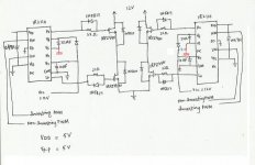
i have made that schematic..but the problem is that one of the ir2110 is getting hot..i have cross checked all the connections..but the connections are same for both the ics..kindly tell me what is the mistake????....
f=4khz , vdd=5v ,vp-p=5v ,vcc=12v ,duty cycle=50%
how can i check that ic if its working or not..shud i change the ic??...
f=4khz , vdd=5v ,vp-p=5v ,vcc=12v ,duty cycle=50%
how can i check that ic if its working or not..shud i change the ic??...
Attachments
regarding your diode problem........are you sure some diodes are not getting too much reflected voltage because of the primary splitting caps drifting, and then you get a lop-sided primary voltage, which can be too high when switching across the higher voltage.
Rail splitting cap voltage drift is a major problem in current mode half-bridge.
...and virtually always requires a balancing winding.
Voltage mode half bridge needs no balancing winding, but needs a series film cap with the primary in case of staircase saturation.
If you do voltage mode, and you have cycle by cycle current limiting when on persistent overload, then the voltage mode becomes current mode, and you again get rail splitting cap drift, which will mean you need to make the primary rail splitter caps rated for the full primary dc bus....which makes them extremely big and expensive, and is why the half bridge is not usually used when the smps must survive continuous overload
- Status
- This old topic is closed. If you want to reopen this topic, contact a moderator using the "Report Post" button.
- Home
- Amplifiers
- Power Supplies
- Half-bridge heat problems