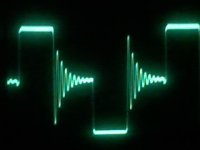
I tried now removing the mosfets' snubbers to see the waveform of the unsnubbed ringing and post it so you can tell me what you think, the diodes heat up a little less (a lot less indeed)
this is the picture of the unsnubbed waveform in the primary side, the signal is 317 V peak-to-peak, the switching frequency 125KHz almost exactly
The output at the time is 16.38V at 3.27A (54W) over a pure resistive load
this is the picture of the unsnubbed waveform in the primary side, the signal is 317 V peak-to-peak, the switching frequency 125KHz almost exactly
The output at the time is 16.38V at 3.27A (54W) over a pure resistive load
Attachments
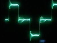
and this is the waveform on the secondary side of the transformer under the same conditions at the same time...
I consider this power very much to be unsnubbed, but everytime I place an RC snubber things get more complicated, and the heat seems to go from the mosfets to somewhere else instead of being fully dissipated on the resistor
Is there some rule of thumb or calculation for a snubber network?
I used one I found in a book about SMPS, but seems not to be a very good solution, by other hand... is there another kind of inexpensive snubber for half bridge SMPS?
Regards!!
Attachments
in snubbering, both the rectifiers and switchers the values will interact and require cut and try
i tried many ways to calculate snubbers, sometimes they work other times they don't.
the calculating theory is fine but all of the books have you build it then add suppression and component protection later.
so having said the obvious....
my number one way is looking at the period and then calculating the apparent rc and start there.
number two Chryssis' formula method sometimes works
as well as Brown's select the cap that increases the period by three then add a resistor until you get it close.
i guess the two questions i would pose,
1. what is the input and out put voltages and currents
2. when you say "HOT" that is a bit subjective, all parts will get hot. the Vd/I is going to make watts so hot may be normal, most parts can/need a heat sink then be normal operating temp
however, LAYOUT, frequency, resonance, inductance, reactance, reflected waves, are the unknowns because of the nasty harmonics square waves generate.
so unless you are really good at Laplace Fourier and Smith and have forever to calculate it out, it is easier and faster to guess..a few times.......
I JUST LEARNED THAT WHEN I WENT TO A 2 PHASE FORWARD CONVERTOR on another thread. my single phase one 'run of the mill' things have worked well.
jamesrnz said:is there any advantage to placing a snubber across a pn diode, fast or ultrafast?
schottkeys, certainly due to the capacitance of the "junction"
Trr is about 60ns
i never place a rc snubber across pn junction diode, only used with Scotty diode, so i dont know for sure, also never work with such high frequency, so i dont have any reverse recovery issues, for a off-line half bridge i never use a rc snubber across the fets, may be placing a snubber across the primary winding and another for secondary would cut down those ringing,
And if I understand right, the way areza suggests is this...
Is 125KHz such a high frequency? I have built and sold 2 kinds of flyback type SMPS working at about 200KHz with no problems... this is the first HB I make, is this frq high for HB?
Can this also be a problem of the output inductor filter? can this happen if the output inductor saturates or is not big enough?
areza: correct me if I misunderstood what you told me about the placement of the snubber across the primary, and if not, how do you suggest to place a snubber over thge secondary?
Thanx!!!
Attachments
areza: for what i've seen in this thread:http://www.diyaudio.com/forums/showthread.php?s=&threadid=131524&highlight=
you are right, that cap is for blocking DC, and the snubber you suggested is the adequate for this topology and I shall place it and the continue with the thread
Thank you all, been really helpful!!!!!
Regards, Fernando
you are right, that cap is for blocking DC, and the snubber you suggested is the adequate for this topology and I shall place it and the continue with the thread
Thank you all, been really helpful!!!!!
Regards, Fernando
here are a few more about snubbers that more obscure but valuable
i like the fuji one.
www.fujielectric.com/device/semi/pdf/REH984/REH984_05.pdf
www.engr.usask.ca/classes/EE/391/notes/snubbers_ti.pdf
www.rose-hulman.edu/~herniter/Rose_...%20of%20Snubbers%20for%20Power%20Circuits.pdf
i like the fuji one.
www.fujielectric.com/device/semi/pdf/REH984/REH984_05.pdf
www.engr.usask.ca/classes/EE/391/notes/snubbers_ti.pdf
www.rose-hulman.edu/~herniter/Rose_...%20of%20Snubbers%20for%20Power%20Circuits.pdf
Thanks jamesrnz, there is information about snubber that I'm looking for since long ago!
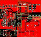
I think that rather than snubbing I have to try to improve the magnetic coupling of the transformers, seems I'm doing something wrong since The unsnubbed ringing is not really big in the primary side, but in the secondary side there's ringing much worse than the primary side one, regardless of the snubber I place at the primary side, it's always the same... now I've built a toroidal transformer that produces really smaller spikes at a higher frequency than the spikes I got with the EE core transformer, I'm starting to think that the tracks have a part in this issue, for that, I'm posting the PCB so if anyone of you know can tell me If there's a problem (too long, too wide, too thin, etc), this circuit is not the real one thats left after all the modifications I made following this post, but resembles a lot, and the tracks are the same, it's the board I'm using after all
On the other side, can be the output inductor saturating, at this current H=1403 Am , can this be too much? I cannot get an MPP toriod so I'm using a gapped EE2507 core, but the minimum gap is 0.5 mm, so the turns are a lot (I needed about 40 for low currents of 1A but I built it of 25)
Thanks
Attachments
I replaced the output ultrafast diodes MUR1620CT for SR560 60V 5A schottkys, at the beggining went well but next thing I know they shorted and the mosfets blown up. Why is this? happened before with schottkys but I didn't think that was the reason... Are not schottky diodes a good choice when there are spikes?
Thanks
Hope someone's still following this thread
Thanks
Hope someone's still following this thread
the schottkeys must be snubbed
i have found that almost all inductive devices under square wave application need some snubbing.
many times i have found that a small amount amount of snubbing will solve a problem.
you may want to review thread 130904 this is one i am working on.
when does it blow up? just running? changing load? disconnecting load?
i would make the board a bit more symmetrical around the divider caps and mosfets. but i'm not sure that is the problem.
what type of spikes are on the diodes before and after them.
does the B+ sag under load? this will increase the current the switches work with.
what material and value is the inductor, if it is saturating it will look like a short to the rectifiers and mosfets.
what does the complete schematic look like?
is the oscillator running at 250Khz
( i am a beginner compared to others on DIY, and if i am wrong I will be corrected swiftly and sternly)
"when does it blow up? just running? changing load? disconnecting load?"
First time it happened was after a few times i turned on and of the power supply, now it blew after running a while with a switched load (switching 3.2A at 400Hz), they weren't even close to be hot
"what type of spikes are on the diodes before and after them?"
The same before and after with both type of rectifiers, not sinusoidal but pointy
"does the B+ sag under load? this will increase the current the switches work with."
What is the B+?
"what material and value is the inductor? if it is saturating it will look like a short to the rectifiers and mosfets."
The inductor is a gapped EE type core from cosmo, the material is CF196, its calculated inductance is 50uH
"what does the complete schematic look like?"
I'll post it when it can be understable... sorry
for you to make an idea it uses a TL494 as PWM and a IR2110 as high and low side driver, the FETs are IRF830s which are really more than enough, the output section can be seen clearly in the PCB, has only one inductor and four 470uF aluminum electorlythic caps after the rectfiers
"is the oscillator running at 250Khz?"
Yes it is, for a TL494 to oscillate in dual switch mode at 125KHz must oscillate at the double...
Thanks!
B+ is your doubler voltage from the ac source.
there will be some sag but it should not go too low or the current in the mosfets will increase.
the fact that you said it blows when you turn it on or when the load changes indicates that there is some spikes are occurring exceeding the peak currents of the devices.
are you monitoring both of your drives at the gates to see if maybe you might be getting both of the mosfets turning on at the same time (cross conduction).
this should not cause a problem with the rectifiers unless they are shorting from over current.
i think you may have more that one problem though.
- Status
- This old topic is closed. If you want to reopen this topic, contact a moderator using the "Report Post" button.
- Home
- Amplifiers
- Power Supplies
- Half-bridge heat problems