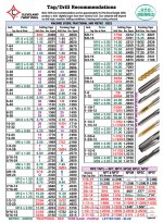
NO !up to 8mm there is a rule - multiply screw metric value by 0.8 and you have drill size
so , for 3mm that would be 2.4mm
anyway , web search is always there , so no need to remember
Look at the tap and read off the thread diameter and the thread pitch. A 3mm tap will usually be marked 3 * 0.5, indicating 0.5mm thread pitch.
Subtract the thread pitch from the thread diameter. 3 - 0.5 = 2.5mm diamter pilot hole.
This gives a "full engagement" thread.
If one requires less thread engagement then select a slightly bigger diameter for the pilot hole, i.e. 2.55mm or 2.6mm, not a smaller diameter as you have stated.
Very hard metal generally work with less thread engagement.
Aluminium and other "soft" metals generally work with full thread engagement.
Using too small a pilot hole can result in a broken tap !!!!!
add a nut on the other side.
I had to repair an aluminium gearbox that had a stripped thread.
Drilled out the ¼"unf tapped hole to pilot size for 3/8"
made up a short 3/8" screw that was tapped to ¼"unf.
Use stud fix to lock that screw into the gearbox casting.
Now I just bolt the casing on using that repaired fixing as if it had never stripped.
A better way would be "helicoil" but I don't have any.
....of eachother ......
damn
for ooomtheenth time
measure Iq on one Rs and output offset
then just check Iq on other side , to confirm that they're in same ballpark
they can't be and they don't need to be the same
..................
I seem to get bias within 5mV of eachother with offset=0
...................
Absolutely !................ they don't need to be the same
They don't need to be the same.
The IMPORTANT criteria is that the Output offset is consistently near zero for all operating conditions, when speakers are connected.
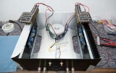
Both boards were set up with a seperate DVM measuring bias and a tjird meter used on the speaker terminals to maintain offset~=o. Within 10mV was fairly easy with a light touch and it remained there while cooking for several hrs.
Heat sink temp was up about 25degC from ambient with bias set to 600mV, all stable.
Ran into a problem:
Removed amp and hooked it up to source (CD through receiver,RCA)
It played music fine and while gradually increasing volume at around 80% a light click was heard from the speakers and there from and out an a dominant hum was heard.
Amp did not leak magic smoke, no odour nor visual clues of defect. With no signal in hum still present.
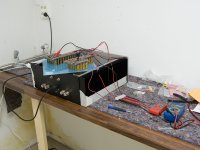
Amp disconnected and placed back on build board.
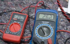
PSU supply normal voltage, bias read zero and offset is 23,3V on both sides.
No visual sign of defects on caps, no heat there.
Bad caps ? Anything else likely to have blown?
Heat sink temp was up about 25degC from ambient with bias set to 600mV, all stable.
Ran into a problem:
Removed amp and hooked it up to source (CD through receiver,RCA)
It played music fine and while gradually increasing volume at around 80% a light click was heard from the speakers and there from and out an a dominant hum was heard.
Amp did not leak magic smoke, no odour nor visual clues of defect. With no signal in hum still present.
Amp disconnected and placed back on build board.
PSU supply normal voltage, bias read zero and offset is 23,3V on both sides.
No visual sign of defects on caps, no heat there.
Bad caps ? Anything else likely to have blown?
This severe offset problem has been reported a few times after a successful few hours of operation.
Blown devices are usually found.
Looks like a speaker protection relay is required until many hours are clocked up.
There does not seem to be an identifiable cause. The amp just goes wrong on a cold re-start.
Blown devices are usually found.
Looks like a speaker protection relay is required until many hours are clocked up.
There does not seem to be an identifiable cause. The amp just goes wrong on a cold re-start.
Since both channels show similar offset indicate :
Failure somewhere before the boards (PSU/ground) or after the boards (speakers/ground)
Both speakers operate as usual connected to the old amp so they are fine. Speakers are 6,4ohm nominal btw with EQ boosted signal (6dB lift at bottom end and similar lift on high end)
The failure in my mind can not be a single component on one of the F5 boards.
I will tear down the amp into its seperate modules and measure my way up again.
Bad transistor.
One specific or all? What cause these to fail in the first place?
And one last thing for now, how to measure?
")
Part of the objective of this build is to learn more about this, so far I am getting my money worth
- Status
- This old topic is closed. If you want to reopen this topic, contact a moderator using the "Report Post" button.
- Home
- Amplifiers
- Pass Labs
- Halair's F5 build