...I don't have engineering data but I can tell you from reading about using Hafler heatsinks in a class A amp, the heat sinks are just not large enough for any amp with a reasonable amount of watts.
What do you think is the safe "class A" max for the xl-280 heatsinks its w/6 MOSFETs?
I want to drive tweeters above 2K? (4th order filtering).
thanks tony
As you know your amp operates in Class A for the first scant watt or two before power demands make it slip into Class A/B operation. The point at which the amp slips out of Class A and into Class A/B is dependent on the amount of bias applied to the output stage. I have read messages about guys who biased their Hafler up to 450 mA of bias, and even installed a fan to help the amp keep cool. Your amp now is probably biased at around 280 mA.
If you really, really want some Class A output for your tweeters, consider swapping the power transformer for one that will provide around 25 to 30 VDC to the circuit, and then upping the bias to the point you think the amp has gotten dangerously hot (usually around 65 celcius).
Will all of this be worth the effort to get a slight improvement in sound? I wonder. . . .
Dick
I have very efficient speakers (96db/1w/1m) and would like to play with a low power Class A using the Hafler DH200 chassis, heat sinks and outputs.
I have read this thread from one end to the other and the promise of new driver boards has never materialized.
Then I read the Pass forum F5 page and I think that driver board would be great to try here. I have a toroidal 24-0-24 vac transformer and plan on 4 39,000 uF of capacitance per Mr. Pass' F5 power supply design.
My question is do I need to change anything to drive 4 Mosfet outputs or due to the heat sinks should I only use a pair of outputs.
Also somewhere on the Pass forum I found this F5 mod and would like opinions. It shows only 20 VDC +- rails is that a problem as I will have 32 + - VDC? (see jpg)
Rush,
I have built the F5 amp and here my comments on your shown schematics:
1) Gain review:
The Pass F5 topology is based on the higher gain of the output VERTICAL mosfet. With Lateral mosfet as the SK134/SJ49 in the DH-200, the resulting OPEN loop gain is small (> 5 times smaller) and limits the amount of feedback. The good thing is that the DH-200 has 2 pairs so it doubles the mosfet gain contribution (but you still miss >2,5 of gain). Furthermore, the schematics you have posted has twice the closed loop gain of the F5 which worsens the problem. To improve the situation, you can reduce the gain of the amp by putting additional 100 ohms power resistors in parallel with existing R3/R4 and/or you can add a 3rd pair (or 4th) of mosfets (matched thus might prove difficult with your existing one...). However, you can still have a decent amp with only 2 pairs since the "PROFET" amp has that (http://www.selectronic.fr/upload/produit/fichetechnique/4180.pdf).
2) Temperature vs Bias current (Class A): The DH/XL-200/220/280 heatsink can deliver about 55W or so for about 50 to 55C. With +/-32v that gives about 0.86A MAX so 13W class A into 8 ohms compared to F5 amp which is 20W class A. However it may be ok with your 96db speakers since it will probably go rarely into class A/B which is not that bad anyway.
Note that the 2SK134/2SJ49 mosfet are the same as the 2SK1058/2SJ162 and they can be bought matched on Tech DIY Company Store .
You can find an example of a DH-200 conversion into a 20W class A amp (but not the F5):
http://sites.google.com/site/fabaudio/jlh-fabclassapoweramp
Good luck
Fab
Last edited:
Fab,
Thank you for your very informative response. This is just what I was looking for.
The gain review:
I will set the 100 ohm feedback resistor to 50 as in the original circuit.
I was thinking that the distortion was already so low that less feedback might sound just as good or better, but since the feedback is already down by a factor of 5 the 50 ohm will be a good starting place. I am used to listening to SE tube amps with up to 1% distortion and as far as I can tell the distortion is undetectable. I am not a numbers guy.
Do you like the use of the 2N5401 and 2N5550? Or would the original F5 be the way to go?
The temperature vs Bias:
Good points.
To keep the amp in class A and the sweet spot perhaps I will get a lower voltage transformer like 15 0 15, should give me 20 VDC + - . At 1.3 amps per device and 20 V should be 52 watts per heatsink. I will only use one pair of outputs per channel. The other set will be spares for the long haul or a second amp.
The “Systeme Triphon II” 4 channel amp looks a lot like the F5 topology in its simplest form. Sure would be easy to bread board that together.
On another note, I am using my Mac Mini exclusively now with my QB9 DAC and loving it. I don’t need a preamp so I will incorporate a volume control and the following gain stage courtesy of Mr. Pass inside the amp: I have a handful of these 2SK170 GR.
................+15VDC
.................1K
..................D - 10uF - 1K - OUT
..................|
IN - 1K - G >|_ 2SK170 N ch
............|.....|
.........100K 47ohm
............|.....|
GND =..__ ..__
F5 type amp
Keep us posted on your progress.
Fab,
Thank you for your very informative response. This is just what I was looking for.
fab: You are welcome.
The gain review:
I will set the 100 ohm feedback resistor to 50 as in the original circuit.
I was thinking that the distortion was already so low that less feedback might sound just as good or better, but since the feedback is already down by a factor of 5 the 50 ohm will be a good starting place. I am used to listening to SE tube amps with up to 1% distortion and as far as I can tell the distortion is undetectable. I am not a numbers guy.
Do you like the use of the 2N5401 and 2N5550? Or would the original F5 be the way to go?
fab: I would start with the original F5 since I am not convinced about the real benefit of this active/passive load...
The temperature vs Bias:
Good points.
To keep the amp in class A and the sweet spot perhaps I will get a lower voltage transformer like 15 0 15, should give me 20 VDC + - . At 1.3 amps per device and 20 V should be 52 watts per heatsink. I will only use one pair of outputs per channel. The other set will be spares for the long haul or a second amp.
Fab: I believe that this "sweet spot" is for the F5 with Vertical Mosfet. I am not sure if it is really the same bias current with Lateral...
With one pair of Lateral the overall gain will be reduced and you mau not even get a gain of 5... You can set the feedback resistor to a 100 ohms instead of 50 ohms (or something in between) to increase the overall gain but at the expense of losing feedback as explained in the first place. You may have to experiment here to match your speaker and required amp gain.....
The “Systeme Triphon II” 4 channel amp looks a lot like the F5 topology in its simplest form. Sure would be easy to bread board that together.
On another note, I am using my Mac Mini exclusively now with my QB9 DAC and loving it. I don’t need a preamp so I will incorporate a volume control and the following gain stage courtesy of Mr. Pass inside the amp: I have a handful of these 2SK170 GR.
................+15VDC
.................1K
..................D - 10uF - 1K - OUT
..................|
IN - 1K - G >|_ 2SK170 N ch
............|.....|
.........100K 47ohm
............|.....|
GND =..__ ..__

Keep us posted on your progress.
Last edited:
I finally found a really nice DH-220 to play with. I bought it and a DH-110 as a package deal. This DH-220 has a rack mount front plate and the later upgraded circuit boards.
I have checked and set bias and DC offset. I also installed a thermistor for inrush current.
I have not heard/read alot about removing the speaker fuses from the signal path.
As I understand it a fuse inline with the output offers the poorest measure of protection. It also adds distortion and while probably trivial in this case should be eliminated. Also, the 20" or so of old, crappy wiring which I'm sure adds inductance can be eliminated by just removing it from eyelets 6 and 8 and adding a jumper at those points.
Surely eliminating the extra wiring and fuses does more for sonics than gold plated rcas and binding posts.
Thoughts, opinions, experiences????
Hags,
Back in the 90s a commercial version of the DH-220 was sold/installed/serviced by SMART for use in motion picture theater sound systems. This version ran the amp's output through the thermal cut off switches mounted to the heatsinks. The premise being I guess that if the amp were over driven and got overheated the heatsinks would get hot enough to trigger this thermal switch and disconnect the speakers, thus removing the load from the amplifier so it could cool off. I wired up one amp this way and could not detect any degradation in sound quality as compared to running the output straight to the speakers.
There is a slight advantage in leaving the speaker fuses as per the schematic as they are in the feedback loop and thus the amp's feedback loop can make some small corrections for less than perfect quality speaker cables.
The spec on this amp is for 2-4 amp speaker fuses. Many users put in 10-20 amp fuses there to mitigate the effect of lower amperage fuses sounding strange. The much higher amp rating fuses were more like a plain old speaker wire. And, of course, many people just soldered a jumper across the speaker fuse holder, thus removing the fuse from the circuit.
It all depends on how much protection you want to have in your amp. For example, if one of the small signal transistors in the input diff amp section goes out of spec your amp could suddenly be pumping upwards of 60 VDC through the output section and perhaps damaging MOSFETs and speakers, etc. A high watt output amp should have some protection against this.
Hags,
Back in the 90s a commercial version of the DH-220 was sold/installed/serviced by SMART for use in motion picture theater sound systems. This version ran the amp's output through the thermal cut off switches mounted to the heatsinks. The premise being I guess that if the amp were over driven and got overheated the heatsinks would get hot enough to trigger this thermal switch and disconnect the speakers, thus removing the load from the amplifier so it could cool off. I wired up one amp this way and could not detect any degradation in sound quality as compared to running the output straight to the speakers.
There is a slight advantage in leaving the speaker fuses as per the schematic as they are in the feedback loop and thus the amp's feedback loop can make some small corrections for less than perfect quality speaker cables.
The spec on this amp is for 2-4 amp speaker fuses. Many users put in 10-20 amp fuses there to mitigate the effect of lower amperage fuses sounding strange. The much higher amp rating fuses were more like a plain old speaker wire. And, of course, many people just soldered a jumper across the speaker fuse holder, thus removing the fuse from the circuit.
It all depends on how much protection you want to have in your amp. For example, if one of the small signal transistors in the input diff amp section goes out of spec your amp could suddenly be pumping upwards of 60 VDC through the output section and perhaps damaging MOSFETs and speakers, etc. A high watt output amp should have some protection against this.
Dick, Thanks for the response. I wont' disagree with you on sonics, that's a subjective debate probably best left alone. From a builder/modder's viewpoint I'd prefer not to have anything extra and/or unnecessary in the signal path.
Unless I misunderstand, I don't understand how a fuse influences the feedback circuit any differently than a piece of wire. In fact, you can argue that without a fuse and 20" or so of wire the feedback circuit is more readily able to react to things downstream.
The way I see it, with an extra 15-20" of, in effect, speaker wire routed through the chassis you're asking for trouble. It can pick up or put out nasties into surrounding sensitive circuits.
As I understand it, the fuse is the least effective loudspeaker protection you can implement.
Finding just the right size is tedious at best and if you go much higher than optimal, whatever that might be, you're defeating the purpose.
Also, you can still have 10-15 VDC going to your speakers without a 4-5 amp fuse failing.
Someone mentioned Jung removing the fuses from the output signal path earlier in this thread. I cannot find any info on his mods for the DH-220.
A 1A fuse can pass an un-clipped program signal at 200W/4R without opening up, yet it will open up with far less than 10VDC. The feedback loop helps reduce the non-linearity of the fuse at high levels. I also like relay and crowbar circuits too. Whatever combination you like.
A 1A fuse can pass an un-clipped program signal at 200W/4R without opening up, yet it will open up with far less than 10VDC. The feedback loop helps reduce the non-linearity of the fuse at high levels. I also like relay and crowbar circuits too. Whatever combination you like.
Ah! Thanks for that explanation, that makes sense now. It takes care of the fuse nonlinearity as well, right in front of me.
How many people successfully use 1A fuses in their output protection circuit? To me it's a cheap, mid-fi, band aid approach that has as much chance of failing as in succeeding.
Without the fuse I hear better high frequency extension and an overall improvement in sound. An ever so slight increase in resolution as well.
Of course it could be all in my head from just knowing that the crud wiring and fuses aren't there but that's where I hear the music.

Last edited:
I am in the process of changing my transformer, power supply caps, power cord, input and output jacks, rec. bridge, using a simplified F5 front end and I was hoping to leave the output devices alone. This is a lot of work. And someone will probably tell me I should do that, but I am hoping not to at this point.
Has anyone felt the need to pull the output devices and reapply themal grease on their DH-220?
This grease does apparently dry out and I've heard/read about people doing it on older amps.
I personaly do this treatment when restoring a DH200. Moreover the output devices are not directly soldered but inserted in a socket, so cleaning also the pins seems almost necessary after all these years...
Ciao
Paolo
Has anyone felt the need to pull the output devices and reapply themal grease on their DH-220?
This grease does apparently dry out and I've heard/read about people doing it on older amps.
Clean the mating surfaces as thoroughly as possible, with pure isopropyl alcohol. This removes old compound and allows new thermal compound to refill tiny irregularities which would otherwise impede efficient thermal transfer. Avoid using liberal amounts of thermal compound as this will be wasted material. The idea is to use just enough to fill in tiny voids and surface irregularities, and squeeze out any excess.
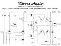
One more Hafler Tube Conversion
New Year - new schematics
Since last post, I have had fun restoring two MOSCODE 300s. Sounds great and has lots of bass slam. For those who know a little about these fun amps, you may remember that they are based on a cascaded 6DJ8 with a 6FQ7 as a white cathode follower driving the MOSFET outputs. The signal has to pass through 4 capacitors. So the idea struck me: why not re-design the cascade and white cathode follower to eliminate at least two capacitors that we did not need? - I still like to keep the two caps between the MOSFETs and the tube section. Sure, a direct coupled output stage could work, - I just do not trust that the tubes will not drift over time. Still, going from 4 caps to 2 seemed well worth it. This also means that one can splurge a bit on the quality of the caps (I went w/ Russian Teflon in glass).
The MOSCODE cascade VAS section yields a lot of amplification. Using to TubeCad and plugging in the 33K and 39K plate values, the compounded open loop amplification came out at ~ 200X. Wow! Also the plate resistors seemed excessively large which made the 6DJ8s operate mostly on the curved section of their gridlines. Great for max amplification - and more distortion... The MOSCODEs reflect some older design ideas popular in the 1980's - lots of amplification and lots of feedback. Great for damping factor and bass - not so good for an airy top end. So lower plate resistors was a design goal.
Speaking of airy top end; here the SE 300B amp w/ zero feedback is a better choice. No bass slam though. This hobby is always about giving something up to get something else. But could a compromise be reached? Could we get good sound-stage and bass slam with a hybrid amp? The earlier SRPP version of my Hafler conversion sounded great. And it had no feedback. Yet, the MOSCODE 300 had better bass...
Since I have a few Haflers sitting around, and I did not wanted to butcher stock MOSCODEs, it was time to build yet another conversion. This time the design goal was:
a) Bass slam - so feedback = yes
b) Clean/warm midrange - so 6SN7s w/ Allen Bradley carbon comp resistors
c) Smooth treble - so as few coupling caps as possible
After some trial and error (as usual), here is what version 6 looks like (see attached).
There is a couple of tricks here I have not come across elsewhere. As you can see from the schematic, the two first triodes look very straight forward: cascaded w/ direct coupling. Each delivering roughly 10X gain so this VAS has only 100X amplification - which in turn meant that we could get by with half the feedback of the MOSCODEs. The 22K plate resistors offer a better plate load to plate resistance ratio for less distortion. Here we have a 3X ratio whereas the MOSCODEs have 10X. Direct coupling also got rid of the first coupling cap. Then there was the coupling cap from the plate of the first triode to the grid of the second triode in the white cathode follower driver. This had to go. Inspired by Broskie and some of his posts on Aikido, it struck me that we really need the bottom triode in white cathode follower to act as an active resistor to the top triodes cathode follower. The white cathode follower normally take this signal from the plate of the top triode via a cap... but since we already had another triode to spare, why not a) lose the plate resistor on the cathode follower (ala Aikido) and b) drive the bottom triode directly with the same signal as the second stage in the cascade? Voila! Done. No more cap and efficient use of the 4 triode available. Simple is best.
I have never seen this configuration before, so I might have "invented" something new. Probably not... But if someone reading this post has seen this approach elsewhere, please post a link.
So how does it sound? Great (as all amp builders will say). Lots of bass slam and a bit more aggressive treble. Midrange - Especially lower midrange is there. It is still breaking in - so perhaps the treble will get sweeter.
If you chose to build this MOSCODE 300 inspired amp, set the BIAS for 300mA (like MOSCODE) and then set the DC offset to 10-20 mV on the output terminals. Also like MOSCODE, you can go AC on the heaters without problems. Just make sure the AC heater is tied to the -60 rail via a 100 ohm resistor so that heater to cathode voltage of the 6SN7s is not too great. This also keeps hum in check. Speaking of hum: use a star grounding scheme and terminate all ground leads between the power supply caps.
Happy 2011
PS: I have posed a .PDF version of the schematic. That should be easier to read than the low res graphic.
New Year - new schematics
Since last post, I have had fun restoring two MOSCODE 300s. Sounds great and has lots of bass slam. For those who know a little about these fun amps, you may remember that they are based on a cascaded 6DJ8 with a 6FQ7 as a white cathode follower driving the MOSFET outputs. The signal has to pass through 4 capacitors. So the idea struck me: why not re-design the cascade and white cathode follower to eliminate at least two capacitors that we did not need? - I still like to keep the two caps between the MOSFETs and the tube section. Sure, a direct coupled output stage could work, - I just do not trust that the tubes will not drift over time. Still, going from 4 caps to 2 seemed well worth it. This also means that one can splurge a bit on the quality of the caps (I went w/ Russian Teflon in glass).
The MOSCODE cascade VAS section yields a lot of amplification. Using to TubeCad and plugging in the 33K and 39K plate values, the compounded open loop amplification came out at ~ 200X. Wow! Also the plate resistors seemed excessively large which made the 6DJ8s operate mostly on the curved section of their gridlines. Great for max amplification - and more distortion... The MOSCODEs reflect some older design ideas popular in the 1980's - lots of amplification and lots of feedback. Great for damping factor and bass - not so good for an airy top end. So lower plate resistors was a design goal.
Speaking of airy top end; here the SE 300B amp w/ zero feedback is a better choice. No bass slam though. This hobby is always about giving something up to get something else. But could a compromise be reached? Could we get good sound-stage and bass slam with a hybrid amp? The earlier SRPP version of my Hafler conversion sounded great. And it had no feedback. Yet, the MOSCODE 300 had better bass...
Since I have a few Haflers sitting around, and I did not wanted to butcher stock MOSCODEs, it was time to build yet another conversion. This time the design goal was:
a) Bass slam - so feedback = yes
b) Clean/warm midrange - so 6SN7s w/ Allen Bradley carbon comp resistors
c) Smooth treble - so as few coupling caps as possible
After some trial and error (as usual), here is what version 6 looks like (see attached).
There is a couple of tricks here I have not come across elsewhere. As you can see from the schematic, the two first triodes look very straight forward: cascaded w/ direct coupling. Each delivering roughly 10X gain so this VAS has only 100X amplification - which in turn meant that we could get by with half the feedback of the MOSCODEs. The 22K plate resistors offer a better plate load to plate resistance ratio for less distortion. Here we have a 3X ratio whereas the MOSCODEs have 10X. Direct coupling also got rid of the first coupling cap. Then there was the coupling cap from the plate of the first triode to the grid of the second triode in the white cathode follower driver. This had to go. Inspired by Broskie and some of his posts on Aikido, it struck me that we really need the bottom triode in white cathode follower to act as an active resistor to the top triodes cathode follower. The white cathode follower normally take this signal from the plate of the top triode via a cap... but since we already had another triode to spare, why not a) lose the plate resistor on the cathode follower (ala Aikido) and b) drive the bottom triode directly with the same signal as the second stage in the cascade? Voila! Done. No more cap and efficient use of the 4 triode available. Simple is best.
I have never seen this configuration before, so I might have "invented" something new. Probably not...
But if someone reading this post has seen this approach elsewhere, please post a link.So how does it sound? Great (as all amp builders will say). Lots of bass slam and a bit more aggressive treble. Midrange - Especially lower midrange is there. It is still breaking in - so perhaps the treble will get sweeter.
If you chose to build this MOSCODE 300 inspired amp, set the BIAS for 300mA (like MOSCODE) and then set the DC offset to 10-20 mV on the output terminals. Also like MOSCODE, you can go AC on the heaters without problems. Just make sure the AC heater is tied to the -60 rail via a 100 ohm resistor so that heater to cathode voltage of the 6SN7s is not too great. This also keeps hum in check. Speaking of hum: use a star grounding scheme and terminate all ground leads between the power supply caps.
Happy 2011
PS: I have posed a .PDF version of the schematic. That should be easier to read than the low res graphic.
Attachments
I did a bad thing... I bought the entrails from a gutted DH200 from a forum member complete with transformer 2 complete PC19C driver boards all fuse holders and transistor sockets with 2 Exicon o/p trannies only missing 6. bias transistor on one board exploded, fried power switch. I have 2 brand new PC19 boards bare . What to do now??? I have a DH200 working with older PC6 driver boards with OE o/p trannies...I'm thinking open heart surgery after I finish my F1 Pass Amp and fix the meter board on my Yamaha B2......
El
El
Hey Eyoung,
Forget the PC19Cs. Toss them and build a true tube driver stage for the old DH-200. If the PS, bridge and 10,000 uF caps are still good, then get a full complement of output mosfets. If you are on a budget, then you can use my schematic above with just two mosfets per channel. That would get you 70W or so. BIAS then is set to 120-150mA. Everything else is the same. BTW: if you plan to use the old caps from the DH-200, then bypass them w/ a nice 10uF/250 PolyProp or similar. Sweeter top. The 2 Exicon's should work just fine.
D.
Juma's F5 meets Buzquito using a pair of k2013/j313
I started this Halfer DH200 rebuild on this thread, then found Juma’s thread:
http://www.diyaudio.com/forums/pass-labs/162042-f5-meets-buzquito-8.html , so I thought I would post my success’ here for future Hafler rebuilders.
Juma’s modification of Nelson Pass’ F5 has more gain and can drive the lateral MOSFETs of the Halfer with no problem. It also sounds great.
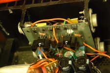
I made my boards the old fashion way, I drew the circuit with a marker and washed it in an acid bath.
Since the MOSFETs are off the board, I made solder connections for them. There has NOT been any smoke released thus far!
I have built this amp using all the parts in the original schematic (see first page of Juma's thread) with the exception of the output MOSFETS 2SK134/2SJ49 as comes in this unit and a +17-0--17 volt DC rail supply under load.
I was having trouble getting any current on the 2SK2013/2SJ313 and 2SK134/2SJ49. As it turned out there was not enough current with the k170/j74GR I used.
I switched to a pair of matched k170/j74BL at 7.16 idss and everything biased up just fine on the both channels.
After some testing I found an oscillation problem, so I inserted a polystyrene 470pF cap across each 150 ohm resistors, problem solved.
The bias is stable with the cover off, cover on it goes up and everything gets hot! I have the bias set at .4 amp per device with it warmed up, cover off, it sounds great! I will have to cut some larger cooling holes in the cover and bottom, although don't know if enough holes could be cut to make a difference. Juma offered that only .25 amp per device would be sufficient unless I am driving 4 ohms or lower due to the lower rail voltage I am using.
I am not using a preamp and I measured .040 vdc on the output of the right channel of my QB9 so at first I added input caps to both channels, then I noticed iTunes volume control is at minimum for background music and will blast into distortion at higher positions. I prefer to use only the top end of the digital volume for critical listening. So I found a pair of UTC A26 transformers; 30K / 500 ohms, primary and secondary have split windings. One of the transformers is open (damaged) on half the primary winding (7 & 9 pins). I measured a 1K sine wave at 3.7 volts on the good half and 1 volt on the secondary so I thought I would try it in front of this amp to reduce the gain and see what it sounded like, also wouldn’t have to use an input cap as the transformer blocks DC. I put a 4k7 ohm resistor across the secondary (500 ohm) and wired two interconnects in/out and gave it a go. The wires are about 2 feet long total.
It sounds pretty good. I can turn iTunes all the way up with no distortion and it is plenty loud enough.
I can switch back to using Audiruana (it doesn't have a volume control) or purchase Decibel ($33), it is better yet (has volume control too.)
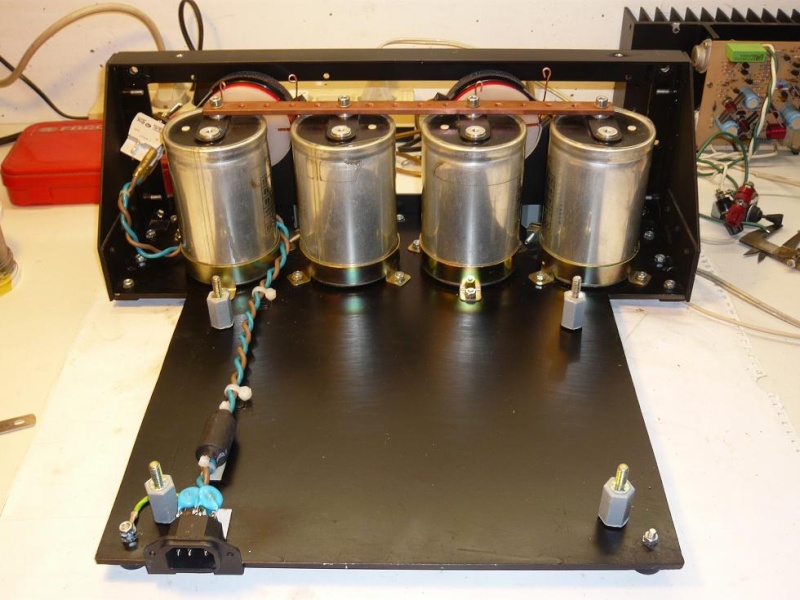
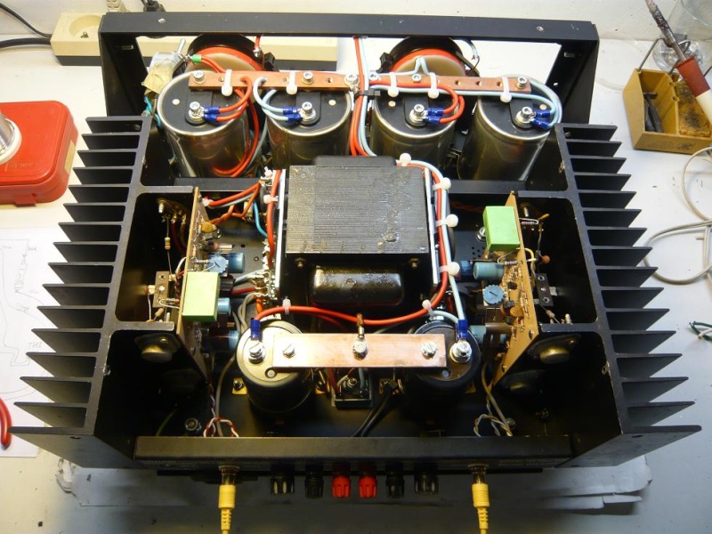
I used a transformer with 6 secondary windings paralleled and a single bridge rectifier with 160,000 uF (with film by-pass caps). There is no hum or buzz coming from this amp or speakers (90 db/1w/1m). I did not use any smoothing resistors in the power supply, just two 3k/5w to ground per rail.
I am very happy with this mod. The sound is detailed with lots of air and plenty of bottom end.
I started this Halfer DH200 rebuild on this thread, then found Juma’s thread:
http://www.diyaudio.com/forums/pass-labs/162042-f5-meets-buzquito-8.html , so I thought I would post my success’ here for future Hafler rebuilders.
Juma’s modification of Nelson Pass’ F5 has more gain and can drive the lateral MOSFETs of the Halfer with no problem. It also sounds great.
I made my boards the old fashion way, I drew the circuit with a marker and washed it in an acid bath.
Since the MOSFETs are off the board, I made solder connections for them. There has NOT been any smoke released thus far!
I have built this amp using all the parts in the original schematic (see first page of Juma's thread) with the exception of the output MOSFETS 2SK134/2SJ49 as comes in this unit and a +17-0--17 volt DC rail supply under load.
I was having trouble getting any current on the 2SK2013/2SJ313 and 2SK134/2SJ49. As it turned out there was not enough current with the k170/j74GR I used.
I switched to a pair of matched k170/j74BL at 7.16 idss and everything biased up just fine on the both channels.
After some testing I found an oscillation problem, so I inserted a polystyrene 470pF cap across each 150 ohm resistors, problem solved.
The bias is stable with the cover off, cover on it goes up and everything gets hot! I have the bias set at .4 amp per device with it warmed up, cover off, it sounds great! I will have to cut some larger cooling holes in the cover and bottom, although don't know if enough holes could be cut to make a difference. Juma offered that only .25 amp per device would be sufficient unless I am driving 4 ohms or lower due to the lower rail voltage I am using.
I am not using a preamp and I measured .040 vdc on the output of the right channel of my QB9 so at first I added input caps to both channels, then I noticed iTunes volume control is at minimum for background music and will blast into distortion at higher positions. I prefer to use only the top end of the digital volume for critical listening. So I found a pair of UTC A26 transformers; 30K / 500 ohms, primary and secondary have split windings. One of the transformers is open (damaged) on half the primary winding (7 & 9 pins). I measured a 1K sine wave at 3.7 volts on the good half and 1 volt on the secondary so I thought I would try it in front of this amp to reduce the gain and see what it sounded like, also wouldn’t have to use an input cap as the transformer blocks DC. I put a 4k7 ohm resistor across the secondary (500 ohm) and wired two interconnects in/out and gave it a go. The wires are about 2 feet long total.
It sounds pretty good. I can turn iTunes all the way up with no distortion and it is plenty loud enough.
I can switch back to using Audiruana (it doesn't have a volume control) or purchase Decibel ($33), it is better yet (has volume control too.)
I used a transformer with 6 secondary windings paralleled and a single bridge rectifier with 160,000 uF (with film by-pass caps). There is no hum or buzz coming from this amp or speakers (90 db/1w/1m). I did not use any smoothing resistors in the power supply, just two 3k/5w to ground per rail.
I am very happy with this mod. The sound is detailed with lots of air and plenty of bottom end.
Attachments
Currently have in a friend's DH-200 for light repair/mods and hope to shortly get a DH-220 for more serious work. Happily mining this thread for ideas and dug up the POOGE-2 article in my back issues of TAA from the good old days of then.
I also have a SE-100 preamp to which I installed a Jung superregulator and am replacing many resistors in the line stage with Vishay z-foils.
I also have a SE-100 preamp to which I installed a Jung superregulator and am replacing many resistors in the line stage with Vishay z-foils.
- Home
- Amplifiers
- Solid State
- Hafler DH-200/220 Mods