what are those things on the far side of the "new" caps?Here is my own contribution !

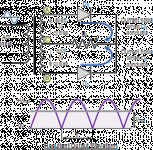
"Large inductors in series with the transformer primaries and secondaries
can be used to stretch the duration of the charge pulse to the power
supply capacitors, improving regulation and reducing noise. Large
inductors in combination with multiple power supply capacitors can form
"pi" filters to reduce the noise on the supply lines."
can be used to stretch the duration of the charge pulse to the power
supply capacitors, improving regulation and reducing noise. Large
inductors in combination with multiple power supply capacitors can form
"pi" filters to reduce the noise on the supply lines."
...and where did you get those copper bars?
Hi gp4Jesus ,
I got copper those bars by an electrician .
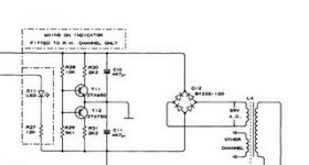
advantages of using 2.2 mh coils .........
For a.wayne , djk gave a perfect explanation for the use of coils ( chokes ? ) .
I use them to improve the filtering .
@ + Philippe.
Lots of nifty mods and improvements. Very impressed. I have a DH-200 and the DH-101.
You can read all about it
Got My Hafler DH-200 & DH-101 - AudioKarma.org Home Audio Stereo Discussion Forums
to bad I broke it. The right channel has 1.3 Volts of DC offset, and the left blue a rail fuse when adjusting the BIAS. saw a spark from the pot, and blew the fuse that the DMM wasn't connected to. Problem: bad soldered legs on the pot. I basically have it all apart in a mess. Just want to throw in some PC-19C boards to replace the PC-6 ones, upgrade the internal wiring, and be done with it. Already have new binding posts and RCA jacks.
Hello Philippe,
Nice work! Where did you find the chokes ?
Merci d'avance
Pascal
Nice work! Where did you find the chokes ?
Merci d'avance
Pascal
Hi gp4Jesus ,
I got copper those bars by an electrician .
For a.wayne , djk gave a perfect explanation for the use of coils ( chokes ? ) .
I use them to improve the filtering .
@ + Philippe.
Hi Pascal ,
I bought the chokes by Audiophonics :
Selfs à Air L140 - MUNDORF L140 Self à Air 1.40mm 2.20mH
Cocorico !
@ + Philippe.
I bought the chokes by Audiophonics :
Selfs à Air L140 - MUNDORF L140 Self à Air 1.40mm 2.20mH
Cocorico !
@ + Philippe.
One of my usual providers ! Fine, I'm going to order a couple of those nice chokes for my DH220.
BTW I've got one (not a mundorf) in the PSU of my tube amplifier and it's very effective. No hum at all...
Pascal
BTW I've got one (not a mundorf) in the PSU of my tube amplifier and it's very effective. No hum at all...
Pascal
Hi Pascal ,
I bought the chokes by Audiophonics :
Selfs à Air L140 - MUNDORF L140 Self à Air 1.40mm 2.20mH
Cocorico !
@ + Philippe.
Hi ,
Here is a topic , ( on the french Elektor forum ) , about PI filtering :
alim et filtre en PI - ELEKTOR.fr | Électronique : Analogique Numérique Embarqué Microcontrôleurs Audio Test Mesure
@ + Philippe.
Here is a topic , ( on the french Elektor forum ) , about PI filtering :
alim et filtre en PI - ELEKTOR.fr | Électronique : Analogique Numérique Embarqué Microcontrôleurs Audio Test Mesure
@ + Philippe.
I did a bad thing... I bought a dh220 on fleabay. I have not got it yet to see what kind of basket case it is , I have not bought anything on ebay electronics that was working when I got It ....That said I have been lucky that I have been able to fix everything reasonably cheap. Stay tuned It looks like a pawn shop special (was working the last time I plugged it in)...
I am an amplifier addict. the fact that i happen to be drinking when I buy these wonderful amps means nothing....
Does anyone know how deep in class A you can bias or is there a sweet spot(to paraphrase another )
)
Burning in South Carolina... EL
I am an amplifier addict. the fact that i happen to be drinking when I buy these wonderful amps means nothing....
Does anyone know how deep in class A you can bias or is there a sweet spot(to paraphrase another
)Burning in South Carolina... EL
I did a bad thing... I bought a dh220 on fleabay. I have not got it yet to see what kind of basket case it is , I have not bought anything on ebay electronics that was working when I got It ....That said I have been lucky that I have been able to fix everything reasonably cheap. Stay tuned It looks like a pawn shop special (was working the last time I plugged it in)...
I am an amplifier addict. the fact that i happen to be drinking when I buy these wonderful amps means nothing....
Does anyone know how deep in class A you can bias or is there a sweet spot(to paraphrase another
Burning in South Carolina... EL
Normal BIAS for the DH-200 is 250mA. For the DH-220, it is 275mA.
You can go higher, but at the expense of more heat, and a slightly shortened life span. I'm not sure what the maximum you can go before something smokes, but I wouldn't go higher that 300mA.
Normal BIAS for the DH-200 is 250mA. For the DH-220, it is 275mA.
You can go higher, but at the expense of more heat, and a slightly shortened life span. I'm not sure what the maximum you can go before something smokes, but I wouldn't go higher that 300mA.
Hi eyoung
For more clarification, the output Lateral Fets are self protected against over temperature. The temperature coefficient (about 110-130 ma range per mosfet) change after some bias current value, so the more the temprature rises the more the current drops. Therefore, even if you try to increase the bias current, after some times, it will automatically reduces due to high temperature. The amount of reduction is also function of the size of the heatsink. I remember noticing that effect around 300ma ( bias for 2 pairs) or more - I think. I have already described it earlier in the thread.
The "sweet spot" for these Lateral mosfets is high bias current thus would require a bigger heatsink...or to reduce the voltage (I remember Nelson Pass indicating that this design can make a nice sounding class A amp)
Also, these amps have thermal cutoff switches when heatink temperature exceeds 70C thus you can try different bias current values without too much risk.
Good luck
Fab
Last edited:
I asked the same "class 'A' question elsewhere on this thread. They advised me (on an XL280) "pull back on the finals PS voltage to about 30; adjust bias until you can't touch the sinks." Also asked the question: "Would it be worth it?"...Does anyone know how deep in class A you can bias or is there a sweet spot(to paraphrase another
cheers tony
Here is another idea. Convert the power supply from a full wave BRIDGE to a simple full wave supply. This way instead of having + and - 60v you would only have about 60v. Then use the type circuite used in one of the Quad amps to make a + and - supply from one voltage. Use the first circuite to get the 60V dc then the last 1/2 of the next circuite to get the split supply voltages. Then we should be able to run the bias a whole lot higher.
Attachments
Class A higher current
You mean a virtual ground for a power amp and using half de power capacity of the actual tranformer.... why not change the transformer to a smaller voltage with same power rating then...
Here is another idea. Convert the power supply from a full wave BRIDGE to a simple full wave supply. This way instead of having + and - 60v you would only have about 60v. Then use the type circuite used in one of the Quad amps to make a + and - supply from one voltage. Use the first circuite to get the 60V dc then the last 1/2 of the next circuite to get the split supply voltages. Then we should be able to run the bias a whole lot higher.
You mean a virtual ground for a power amp and using half de power capacity of the actual tranformer....
why not change the transformer to a smaller voltage with same power rating then...Class A
Yes FAB, that's what I did. Worked out very well. I use it as a tweeter amp, running 17.5 VDC on each rail.
You mean a virtual ground for a power amp and using half de power capacity of the actual tranformer....
Yes FAB, that's what I did. Worked out very well. I use it as a tweeter amp, running 17.5 VDC on each rail.
- Home
- Amplifiers
- Solid State
- Hafler DH-200/220 Mods