It might be easier to get an isolation transformer which will step the mains voltage down to 110.
Or even, as isolation isn't required, a variac. Out shopping recently I was surprised how cheap a 1kVA variac was. Cased up, it listed a bit lower than what I paid for a custom 1kVA toroidal.
I thought there is a dual winding transformer that simply requires the change of a couple of jumpers.
The man. shows two possible transformer types - the 'domestic' (T401) and 'international' (T402). If the OP has the domestic US variant, it has a single primary.
Other than the mains voltage, is there another reason you want to replace the EI transformer with a toroidal? It might be easier to get an isolation transformer which will step the mains voltage down to 110.
Actually, the price of the toroidal and the price of a decent step down (1KVA) is almost the same locally.
So, am more inclined to replace the transformer to avoid clutter.
Another option that I am thinking is having the EI transformer, re-wound for 220VAC primary. Labor in our country is so inexpensive.
")
Am trying to avoid having a 110V audio equipment, am a klutz and I might plug it on my mains outlet and burn the Hafler.
Last edited:
Another option that I am thinking is having the EI transformer, re-wound for 220VAC primary. Labor in our country is so inexpensive.
Copper's not though so hopefully you'll get scrap value back on the 120V windings (which will be thicker wire as fewer turns).
Copper's not though so hopefully you'll get scrap value back on the 120V windings (which will be thicker wire as fewer turns).
Actually, copper is not that expensive, the core is more expensive.
I just talked to a friend who owns a transformer factory, he will wind for me and just give me the bobbin with the windings, I will try to recover the core from the original transformer and stack it myself to the new bobbin...
Actually, copper is not that expensive, the core is more expensive.
It certainly seems relatively expensive here, when I bought a 100m reel of wire it was more than lunches for a week.
I just talked to a friend who owns a transformer factory, he will wind for me and just give me the bobbin with the windings, I will try to recover the core from the original transformer and stack it myself to the new bobbin...
Sounds like a fun exercise. I still remember the old days when RS sold transformer kits for building your own EI. Only had to wind the secondary though - doing your own primary is more challenging I think. Stacking the laminations and not getting any rattles or hum may be an even bigger one...
I just replaced the 4 100uf electrolytics on the driver board with 4 220uf Panasonics (I have on hand used for bypassing tube projects, the Hafler is my first SS project). Sound is pretty much imporoved.
The board have a 470uf bi-polar cap, I cannot find better replacements, how low of a capacitance can I go? I have a bunch of polypropylene and polyester caps, the highest is 20uf... I wonder if I can use these instead.
Thanks.
The board have a 470uf bi-polar cap, I cannot find better replacements, how low of a capacitance can I go? I have a bunch of polypropylene and polyester caps, the highest is 20uf... I wonder if I can use these instead.
Thanks.
... I wonder if I can use these instead.
You certainly can, but bass performance will suffer. This cap determines the low frequency roll-off of the amp. Reducing it by a factor of 20 sounds rather drastic...
But try it and see what it sounds like. You could try substituting back-to-back 1000uF polarised electrolytics if you don't like the sound of your 20uF.You certainly can, but bass performance will suffer. This cap determines the low frequency roll-off of the amp. Reducing it by a factor of 20 sounds rather drastic...
Back to back, does it mean, - connected to the -?
I asked if I can lower it because in vacuum tube circuits, hardly I would go beyond 2.2uf for an output cap.
Thanks.
"hardly I would go beyond 2.2uf for an output cap."
Calculate the RC corner.
The R is 150 ohms. 20µF would then be 53hz.
Thanks, is this the reason (R is 150 ohms) why the nonpolar cap is 470uf?
Am a newbie when it comes to SS circuits, the Hafler is my first SS amp that I am trying to recondition.
Back to back, does it mean, - connected to the -?
Yes, you got the idea.
I asked if I can lower it because in vacuum tube circuits, hardly I would go beyond 2.2uf for an output cap.
Probably the resistor values are considerably higher in a tube amp, so the cap can be correspondingly lower for the same time constant.
Yes, you got the idea.
Probably the resistor values are considerably higher in a tube amp, so the cap can be correspondingly lower for the same time constant.
Ok, thanks.
I can get 330uf non-polar (Panasonic) from Farnell and 1,000uf non-polar (N Series Blackgate) from a friend.
I know that installing higher capacitance might be ok but installing lower value might attenuate the low frequency.
I will go with the 1,000uf Blackgates.
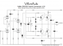
HAFLER 200/220 Tube Driver
Back in April I posted a minimalist schematic tube driver circuit for a HAFLER 200/220. It sounded good. But the bass was a little soft...
Likely the simple cathode follower was not enough to fully drive the MOSFETs. And I did not want to resort to feedback and more amplification. The objective here was to have the current delivery of push pull MOSFET combined with the 3D sweetness of tube amplification with zero global feedback.
All this is clearly inspired by MOSCODE and Harvey Gizmo Rosenberg's philosophy. In fact, he and George Kay used an old HAFLER to build the prototype for the MOSCODE 300 http://georgekayeaudio.com/Resources/1st_Moscode-big.jpg
If you have $5.5K to spend, the MOSCODE 402au is likely to be a sweet amp indeed. If not, and you know how to work with tubes, then a HAFLER mod seems to be a more cost effective way to go.
The project should not cost you much. Say $150 for the HAFLER and then another $150-$200 in parts. The only challenge is how to fit 4 octal tubes into the chassis as well as an additional transformer and caps for the B+ and heater supply for the tubes. I am working on figuring out just how at the moment... safe to say the chassis will be packed.
For now the amp is running on my desk in prototype form (rat's nest) - but it sounds great! Ballsy bass, details galore and deeeep sound stage.
To get direct coupling with only 380V, I opted for an SRPP voltage gain stage with a white cathode follower similar to MOSCODE which indeed does a great job driving the MOSFETs.
Here is the schematic if someone wants to give it a try.
Attachments
Rick: Yes - I saw the missing cap value after I posted. The value should be the same as the other signal RC constants: .22uF - 600V
Scott: The BIAS should be 280mA to 300mA for class A-B. You can run the output stage hotter if you like.
I have not been able to hear the advantage of running the HITACHIs hotter. Actually NATIONAL measured a THD increase with hotter BIAS (see page 5-6 here: http://www.national.com/an/AN/AN-1645.pdf) The 2SK1058/2SJ162 Renesas MOSFETs are essentially the same as the older HITACHI MOSFETs used in the HAFLER. Table 3 on page 6 tells the story. - Still, I like to run my at the HAFLER prescribed 280mA or so. Remember that the tubes likely add relative more distortion than the source follower output stage anyway. I am not looking to get rid of the last vestige of distortion, but instead have an amp that sounds airy, ballsy and detailed.
As an old fan of SET design, I listen first and then measure second. - Hey, there is an idea: drive the source followers w/ a SET 300B design...
How about a DN2540 as the follower with a cascoded DN2540 in the bottom as the current source? Three DN2540's to replace one tube with more current to drive the outputs, and since the DN's are fets we still have some of the tube sound in the follower stage. Also how about a 6DJ8 for the front end to save space and use lower voltage?
Ok, thanks.
I can get 330uf non-polar (Panasonic) from Farnell and 1,000uf non-polar (N Series Blackgate) from a friend.
I know that installing higher capacitance might be ok but installing lower value might attenuate the low frequency.
I will go with the 1,000uf Blackgates.
the 1000uF blackgates type N blackgates are very good stuff- special construction. no longer made anymore.
- Home
- Amplifiers
- Solid State
- Hafler DH-200/220 Mods