GU81m would be an interesting candidate to try with my CCS heater supplies.
Maybe this will be too much heat dissipation? Because of the 10A current. If You have say 3V cca. collector-emitter this will be about 30W dissipation (minimum) at the pass transistor? So the heat-sink for just warm operation should be huge?
.
I am just considering different ways gor heating kathode because I will try to make one SE amplifier.
You are correct, you will need a sizeable heatsink for these regulators, but i wouldnt worry too much about mosfet dissipation, the mosfets used will eat 30-40W for breakfast. And there is two of them.
Yes the devices will stand but I am worried about this acumulation of additional heat... I want to design a reasonably small dimensions and dual mono. We have driver tube also have not small heating current and power needed.
.
As I understood AC heating for GU-81M is out of the question? Or could be used?
.
I measurred internal capacitances in the GU-81 version. And, as i am remember well it was 8nF each 16nF measured in parallel from G2 to CT CAT.
I will check.
.
Good thing is that internal resistance of the tube is around 700-800 ohms and output transformer not deserves much Henry-s") With lower number of turns on apropriate core chrs, that will give lower capacitance and lower Ls. With smaller Rdc of the turns. I think that 15-20Hy will go under 10HZ with minimum phase shift. I done some Spice research...
With lower number of turns on apropriate core chrs, that will give lower capacitance and lower Ls. With smaller Rdc of the turns. I think that 15-20Hy will go under 10HZ with minimum phase shift. I done some Spice research...
.
As I understood AC heating for GU-81M is out of the question? Or could be used?
.
I measurred internal capacitances in the GU-81 version. And, as i am remember well it was 8nF each 16nF measured in parallel from G2 to CT CAT.
I will check.
.
Good thing is that internal resistance of the tube is around 700-800 ohms and output transformer not deserves much Henry-s
With lower number of turns on apropriate core chrs, that will give lower capacitance and lower Ls. With smaller Rdc of the turns. I think that 15-20Hy will go under 10HZ with minimum phase shift. I done some Spice research...11.8V at 12A is going to create some hum on your outputs, but that primarily depends on the gain of the GU81m in your circuit.
As for heat, yes you will dissipate another 40W with the regulator, if you want less heat you could go for a switcher or AC heating.
One little advantage of my circuit is that it can be set to limit the current at say 15A during startup, that means that the filaments wont flash during startup like they normally do when AC or DC heated. This is better for the lifetime of the tube.
I am thinking of building a switch mode (FLYBACK) for 24V 5A out, and using this in conjunction with the regulator circuit to provide 7.5-22V 5A of heater current from 95-265VAC in. But the people i talk to don't like the idea, as switchers are taboo in tube amp applications.
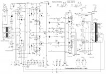
Schematic of my 1500W GU81 power amp
Hi Folks,
here are the drawing of my 1500W amp with 2x GU81 in the final.
The Power supply is not shown. It need several heater voltages due to Vf/k .
Input/Voltage amp 1000V+ (E80F / 2x EL803=
Driver 600V+ (EL34)
-Vg1 280V-
Vg2 600V+ (from HT power unit)
Output plate 2700V+ (2x GU81)
A makeshift power supply run on single phase, 4,2kW /5,1kVA which is abt.25A. It is real difficult to get this load from single phase sockets. 16A is the maximum from a "Schuko" socket" But common CEE sockets bring all 3 phases , thats 11,5 kVA. I use a 400V to 230V transformer at the moment to get the 25A at 230V. The trafo is a 6kVA "control transformer" for industrial switchgear, bought on the local scrapyard by the kilogramm. What a heavy beast.
The final power unit run both channels from 3 phase 230/400V supply , thats only 15A /phase.
You may find some mistakes in the drawing, but in the real amp is working.
Edit: the heaters of the finals run with ac, no hum. The S/N is abt. 75dB (25mV hum&noise at the speaker terminals with no input signal.
73
Wolfgang
Attachments
Last edited:
I had 2 mV of hum with my KT150 PP setup; it’s now down to an inaudible 0.35 mV by elevating my DC heaters.
My 2mV were clearly audible, so 25 mV will be quite audible too. But when you actually play with 1500 Watt I guess you will have a lot of distance between the speakers and the listener. I doubt the listeners will then notice the hum.
I don’t have speakers for so much power...
Regards, Gerrit
My 2mV were clearly audible, so 25 mV will be quite audible too. But when you actually play with 1500 Watt I guess you will have a lot of distance between the speakers and the listener. I doubt the listeners will then notice the hum.
I don’t have speakers for so much power...
Regards, Gerrit
Hi,
Yes 25mV are audible noise if you standing right in the front of the speaker. But You really will not stand in close range to the speakers if the amp is playing Rock with the level is cranked to 11. The amp sounds amazing with a distance of 50m from the speakers. "Wacken open air" in my backyard.
Wacken Open Air
I hope the S/N ratio raise when the amp ist is fittet in a rack with all covers on.
I use a number of JBL Control 12SR and 2 homebrewed bins similar to JBL 4771 with each got 2x 2226 and 1x 2380, 1x 2445 Driver, and 2x 2402 tweeter. Allone those 2 bins are able to eat 1200W program.
I mean 75dB S/N is not bad for such amp. The input sensitivy is 500mV with level control at full blast
In my workshop I use a dummy load and attach a 5W/ 100V speaker to the terminals for monitoring. 1500W into 8 Ohms are 109Vrms
Yes, look at #121 in this thread.
My two homebrew MC3500 are lot quieter. 2mV into 8 Ohms , thats about 90dB . It is more noise than hum. They are little better with bottom and top cover fitted. But I did made no testings with it.
73
Wolfgang
errrr....25 mV hum is not quite what I would consider 'no hum'. Suspect slightly less efficient speakers. Hopefully not Bose 901...LOL
Yes 25mV are audible noise if you standing right in the front of the speaker. But You really will not stand in close range to the speakers if the amp is playing Rock with the level is cranked to 11. The amp sounds amazing with a distance of 50m from the speakers. "Wacken open air" in my backyard.
Wacken Open Air
I hope the S/N ratio raise when the amp ist is fittet in a rack with all covers on.
I use a number of JBL Control 12SR and 2 homebrewed bins similar to JBL 4771 with each got 2x 2226 and 1x 2380, 1x 2445 Driver, and 2x 2402 tweeter. Allone those 2 bins are able to eat 1200W program.
I mean 75dB S/N is not bad for such amp. The input sensitivy is 500mV with level control at full blast
In my workshop I use a dummy load and attach a 5W/ 100V speaker to the terminals for monitoring. 1500W into 8 Ohms are 109Vrms
Do you have any pictures of this beast?
Yes, look at #121 in this thread.
My two homebrew MC3500 are lot quieter. 2mV into 8 Ohms , thats about 90dB . It is more noise than hum. They are little better with bottom and top cover fitted. But I did made no testings with it.
73
Wolfgang
Per our very own Tubelab, this is not always so...You are correct, you will need a sizeable heatsink for these regulators, but i wouldnt worry too much about mosfet dissipation, the mosfets used will eat 30-40W for breakfast. And there is two of them.
The issue is centered on running in the un-saturated regime; as they( MOSFETs ) get hotter they conduct more. Then wee bits of the die overheat, and then they fail. The high-magnification pictures of this look like meteor strikes... Not impossible, but not an easy breakfast at 40W of dissipation.Also, IIRC the filament takes 12A at 12V( likely 12.6V ).
Douglas
I have had no difficulty getting quiet amps with hum-pots and individual windings too. Up to 10V for 813's...no reason to expect that 12V will be any different. If you are running a CFB output Iron, suggest common-mode chokes to go between the filament TX and the filament.
Douglas
Douglas
YesHi, there is no need for fire the heaters of the GU81 with dc. There are only a need of a grounded center tapped heater winding on the power trafo. The hum is cancelled out due to the against ground balanced winding.
Each tube need its own heater winding.
73
Wolfgang
Maybe to order transformer with 12.6V CT and slight lower taps additionally.
To try AC or DC
DC tryout with 12.6V trafo is not a best solution. In case of say 3 RC stages after Rectifier/C-rectifier
each resistor will have about 20W disipation
in praxis that will be 75W rated for warm opperation. And probably mounted on the heatsink?Also not small disipation. But could be spread out in numerous points
.
(For 3 stage RC after Bridge-C.
12.6V x 1.41 = 17.76V - 12.6V = 5.16V / 3 = 1.72V / 11A = 0.156 ohm
19W each of 3 resistors…
these 18.9W x 4 = 75W cca resistor power for warm-slight hot opperation)
.
On the other hand GU81M is sensitive for AC variations
12.6V (min 11.6V - max 13.4), 11A
with say 235V : 12.6V = N 18.65
but with same transformation ratio N=18.65
with just +- 5V ac variation 230 and 240V
it will be roughly
12.33V (230V) and 12.87V(240V)
.
with +- 10V ac variation
12.06V (225V) and 13.13V(245V) higher value is almost reached max. of 13.4V by manufacturer data...
813 !! such tube is far beyond at all. If the tube is driving in grid current a EL34 /6CA5 or a 6L6 is more than enough. Without driven in grid current a EL84 6BQ5 will do a good job.I am considering 813 for the driver to GU81
because i have some pieces but i have to order socket. It is not easy to find in local.
The more pricely TV tube like the PL84, PFL200 or PCL82 are a god chice for grid currentless drive.
The GU81 need a voltage swing of abt 300V peak-Peak ( singel ended) .
GU81 in p-p with gridcurrent drive need a voltage swing of abt. 500V p-p. A TV line sweep tube will be fine.
73
Wolfgang
I am planning SE amplifier of about 240Vp-p input signal for cca. 22W ouput.
Don't have much choice of tubes I would love more to employ 814 but I don't have it
Probably I would use some gas HV rectifier like 2 x 3B28 again, because I have the tube and sockets too...
Core for the OT prepared also. Some Waasner EI laminations of about 800 relative permeability. Huge maybe more than 25cm2?
I shall post schematic later.
.
It is the super cool that is Ri of GU-81M very low and with just 15Hy to 18Hy in primary it can go very very low
.
Don't have much choice of tubes
I would love more to employ 814 but I don't have itProbably I would use some gas HV rectifier like 2 x 3B28 again, because I have the tube and sockets too...
Core for the OT prepared also. Some Waasner EI laminations of about 800 relative permeability. Huge maybe more than 25cm2?
I shall post schematic later.
.
It is the super cool that is Ri of GU-81M very low and with just 15Hy to 18Hy in primary it can go very very low
.
Hi, wow, what an efficiency! The GU81 Tube consum abt 140W heating power....for 22W Output!
Okay, if you like it. But you should keep in mind that this huge beast need plate voltages from 1000V upwards to archieve low distortion output . In single ended class A 1500V -2000V is recommend.
The available curves of the tube are normally for RF-designs. But if you look at franks tube data at P-300-1 made by BBC , you will found lot more details for the tube. Because the P-300-1 is an improved GU81 with another base.
https://frank.pocnet.net/sheets/120/p/P300-1.pdf
Due to the high voltage you need a bigger output iron to get all the insulation in between the wires. for 100W the EI150 core is a good choice. Use double insulated enamelled wires for the hv windings.
If you really want low output power such as 22W, use your 813 in the final. It would perform much better with lower plate voltage.
I recently made a performamance test with a RS1003 transmitting tube . I wound a opt by myself with parts ly araound my workshop. I used a gapped M102b core with high quality 0,35mm laminations similar to M111-165.
the max output at resonable distortion were 18W. No nfb installed. The tube run as a pentode, 400v plate, 350v sceen and 2k rp (load impedeance). the driver tube were an EF80.
I will tell you , an iron for a single ended is much, much more bigger, and much more bigger if you want a body shaking bass . Here I used an M102b core. If I would make an single ended 100 watter it would get an SE 150 split tape core.
Sockets for GU81 a very rare to get. If you have relations to a good machine shop , make your own.
73
Wolfgang
- Home
- Amplifiers
- Tubes / Valves
- GU-81m tube amp schematics???