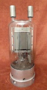
Actualy it is not true... some guys measure the tube in triode mode and they said something of 750V is abs max for this tube.Hi, wow, what an efficiency! The GU81 Tube consum abt 140W heating power....for 22W Output!
Okay, if you like it. But you should keep in mind that this huge beast need plate voltages from 1000V upwards to archieve low distortion output . In single ended class A 1500V -2000V is recommend.
There is no point to push more wats from the tube by force.
That will deserve much higher currents Io points. Which is reducing the number of recitifiers options.
And unnecessary keeping the tube in high current working position even with lower wats...
And of course distortion is higher...
Plus the input signal is much higher for more power.
.
That does not means a lot. relative permeability is the key data. This is the main factor for primary inductance. And that is for proper measurements in LF. Actually this is the crucial poit (with internal resistnce of the tube) for any SE amp. Because of the lack of even good bass performances, the measurements of transfer of the amplifier is so rare. Reason is simple lack of bass and huge phase shift in LF range.I wound a opt by myself with parts ly araound my workshop. I used a gapped M102b core with high quality 0,35mm laminations similar to M111-165.

You should first test the core for different amount of turns and with different (known) magnetic gap. Then calculate relative permeability for this core.
After that calculate based on the internal resistance what walue of Lp(Hy) You need for specific tube.
From current opperating point data You can calculate the value of gap. Then You will see is it apropriate for this tube?
As the current is higher the wire is wider and will eat the space in the window... So it is far from simple calculations we saw every day...
813 have significantly higher Ri internal resistance than GU-81M so the transformer for good bass will be much complicated.
.
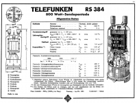
Thanks.Because the P-300-1 is an improved GU81 with another base.
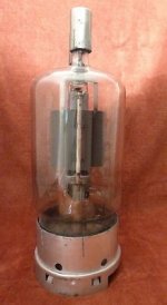
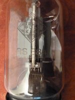
The GU-81M is actually copy of Telefunken RS384 tube. Even has the same socket... I think before IIWW?
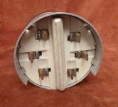
Fortunatley I have multiply pairs of original GU-81M sockets. And original black bakelite "bunny" ears caps. 4 pieces for SE stereo.Sockets for GU81 a very rare to get. If you have relations to a good machine shop , make your own.
It would be nice to choose all the employed tube in the amp to be with caps?
3B28 have, GU-81M, 814, just find the input tube with anode cap and apropriate gain and Ri to drive the driver tube.
Attachments
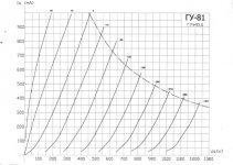
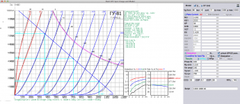
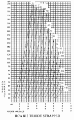
Here are Anode curves for GU-81M in triode mode, measured.
And a spice model parameter datas
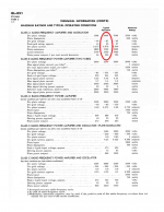
It can go to 45W power with only 2.5% THD which is amasing
BUT the working current point is 450mA...
with peeks up to the 720mA !!!
I didnt calculate but this could be as 0.8mm wire for current density of 2.55.
And a spice model parameter datas
It can go to 45W power with only 2.5% THD which is amasing
BUT the working current point is 450mA...
with peeks up to the 720mA !!!
I didnt calculate but this could be as 0.8mm wire for current density of 2.55.
Attachments
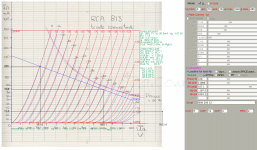
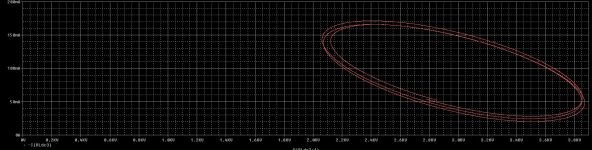
This is the app. 20W 813 settings
It is clear that the huge difference in Ri internal resistance of the tubes.
Zout of the 813 is 1460 ohms
Zout of GU-81M is 302 ohms
This 1460 ohms need a rougly 80 and more Hy for 30Hz say
It is complicated and still on the edge OT...
.
But for these say 300ohms generator impedance the 15-18Hy is good to 10Hz
With wider wire needed for higher currents, the transformer will have VERY low wire DC resistance.
Secondary much more LOW this is the crucial for good damping factor of the amplifier.
.
on the other hand, the measured anode chrs by Frens Mazenier showing the lower Ri of the 813
at 100mA, -80V(g), 825V(a) = 510 ohms?
Should be compared with 813 in tride mode by RCA
Attachments
Last edited:
IMHO , since both GU81 and 813 tubes already is pentodes than both tube for best sonic results have to be connected as pentodes , and working in A1 class , for example GU81 will work good with around UBa=+1,5KV and UBg2=+750V , connected as pentodes driving of g1 is relatively easy , so simple two stage RC coupled and low THD powerful SEP amp can be constructed ,
on the other hand if is insisted on pure triode SET amp than use pure transmitting power triode , something like 833A , or Russian GM100 , or Eimac 3-500 , or ...
on the other hand if is insisted on pure triode SET amp than use pure transmitting power triode , something like 833A , or Russian GM100 , or Eimac 3-500 , or ...
@banat
Hi the main factor is Internal resistance of the tube. It will be imposibile to construct even any moderate OT.
Because the Ri in tetrode/pentode mode is extremely high.
The similar thing is for these triodes - very high Ri too.
GM-100 has Ri=3680ohms, 833A Ri=3280ohms, Eimac 3-500 probably more...
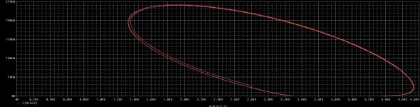
look what it is happening with 833A full input and reduced amount of input with 120Hy of Lprimary
so the output power significantly has to be reduced. For normal opperation.
Unfortunately, diyers and brands by the rule does not show the OT datas, just writing the "max" power...
Hi the main factor is Internal resistance of the tube. It will be imposibile to construct even any moderate OT.
Because the Ri in tetrode/pentode mode is extremely high.
The similar thing is for these triodes - very high Ri too.
GM-100 has Ri=3680ohms, 833A Ri=3280ohms, Eimac 3-500 probably more...
look what it is happening with 833A full input and reduced amount of input with 120Hy of Lprimary
so the output power significantly has to be reduced. For normal opperation.
Unfortunately, diyers and brands by the rule does not show the OT datas, just writing the "max" power...
Attachments
Hi Zoran
I don`t share your opinion that SE OPT is so difficult to be manufactured for those power pentodes working in pentode mode ,special not for 813 beam power tetrode , since any good SE OPT is already complicated and difficult to be manufactured anyway ,
but again if you insist on pure power triode SET amp than OK .
The presented load vs primary L is the reason for that ellipse. Driving with lower impedance is useful too, but Primary L v load applied in || to delivers low freq performance. Like running 8 Ohms on 16R tap, primary load is half, primary L is same, and LF performance improves. measure it...@banat
Hi the main factor is Internal resistance of the tube. It will be imposibile to construct even any moderate OT.
Because the Ri in tetrode/pentode mode is extremely high.
The similar thing is for these triodes - very high Ri too.
GM-100 has Ri=3680ohms, 833A Ri=3280ohms, Eimac 3-500 probably more...
look what it is happening with 833A full input and reduced amount of input with 120Hy of Lprimary
so the output power significantly has to be reduced. For normal opperation.
Unfortunately, diyers and brands by the rule does not show the OT datas, just writing the "max" power...
the results match the math.Douglas
No, The elipse is product of reactive load. With only resistive load the line is "always" flat...The presented load vs primary L is the reason for that ellipse. Driving with lower impedance is useful too, but Primary L v load applied in || to delivers low freq performance. Like running 8 Ohms on 16R tap, primary load is half, primary L is same, and LF performance improves. measure it...
Douglas
.
The Generator resistnce/impedance is aprox Ri II Rload. That Rload is NOT 8ohm BUT load the anode transformed with N of transformation...
.
For instance if the Ri=3800 ohms, and Anode Rload=8000ohm Req-gen=2720 ohm. These 2720ohms with some L(Hy) have to form frequency dependent network
To compare with say 300B with Ri=800ohm aprox. And Rload=3600ohms Req-gen=655ohm, and gor good BW at bass You have to invest circa 40-50Hy...
It is Huge difference
You can check the ellipse "fatness" in simulations with Xaxis=Anode voltage (Ua-Uk) and Yaxix=-Io current @ Anode after reactive load.
Elipse will occur in the HF part of the BW but factors are Capacitances and lose inductance...
The minimum inductance of primary is one that elipse is not deformed and not touching the X axes. In the choosen F and with choosen input Vp-p
Also that is maximum power that is the true to sign... The same for HF side.
NOT the calculated power with static load line...
.
That is for the efficiency is not the relevant value WITHOUT simulating output stage with close values of reactive components.
(and on that should be added magnatization issues and core issues which is not easy to simulate with relevance...)
Right, the ellipse is due to the primary L. Reactance.No, The elipse is product of reactive load. With only resistive load the line is "always" flat...
.
The Generator resistnce/impedance is aprox Ri II Rload. That Rload is NOT 8ohm BUT load the anode transformed with N of transformation...
.
For instance if the Ri=3800 ohms, and Anode Rload=8000ohm Req-gen=2720 ohm. These 2720ohms with some L(Hy) have to form frequency dependent network
To compare with say 300B with Ri=800ohm aprox. And Rload=3600ohms Req-gen=655ohm, and gor good BW at bass You have to invest circa 40-50Hy...
It is Huge difference
You can check the ellipse "fatness" in simulations with Xaxis=Anode voltage (Ua-Uk) and Yaxix=-Io current @ Anode after reactive load.
Elipse will occur in the HF part of the BW but factors are Capacitances and lose inductance...
The minimum inductance of primary is one that elipse is not deformed and not touching the X axes. In the choosen F and with choosen input Vp-p
Also that is maximum power that is the true to sign... The same for HF side.
NOT the calculated power with static load line...
.
That is for the efficiency is not the relevant value WITHOUT simulating output stage with close values of reactive components.
(and on that should be added magnatization issues and core issues which is not easy to simulate with relevance...)
The Ellipse is tilted at the magnitude of the load line. Resistive is straight, and gets to 'flat' as resistance becomes infinite.
So then, how is it that pentodes, with plate Z much higher than applied load work? Take for example the Citation II or W6m. a-a load of ~3,300 Ohms. When in high power output, their Class AB leaves the load seen by the conducting side at a quarter of this...800 Ohms-ish. Yet plate Z is large, even with the U-L connection...
Now consulting the data sheet of a 5k a-a output transformer, some benefit is seen from low source impedance. It is not the primary driver of the low frequency performance. The large( compared to gapped SE ) primary L is doing the heavy lifting here. As far as the tube sees it, Reflected load is in || with the Primary L. Shrink primary L and LF response suffers.
Douglas
Hi @banatHi Zoran
I don`t share your opinion that SE OPT is so difficult to be manufactured for those power pentodes working in pentode mode ,special not for 813 beam power tetrode , since any good SE OPT is already complicated and difficult to be manufactured anyway ,
but again if you insist on pure power triode SET amp than OK .
Im not insisting, just trying to be practical and give some argumentation. First with avability of tubes, second with reasonable probability of making very good OT transformer. Many factors have to be reconsidered and equalised.
.
IF You ask me which output tube I would like to use in my own SE amplifier answer will be UB-180. BUT this tube is hard to find and it is expensive.
OR AD100 and AD60 triodes - the same reasons...
.
BUT i dont have these types and their sockets
...
For beam tetrodes maybe it is posibile to design something like super triode connection
https://tezukuri-amp.org/evo/amp/kt90/report.htm
...
These booth are the Push-Pull amplifiers, with the global feedback, (Heatkit W6m has something additional called dumping control...).Take for example the Citation II or W6m
I was talking there about Single Ended amplifirs without global or local feed-back
Yes.primary L is doing the heavy lifting here. As far as the tube sees it, Reflected load is in || with the Primary L. Shrink primary L and LF response suffers.
And this fact dictating indirectly behaviour in HF by fact that higher L deserves more turns, more turns producing more capacitances and eating the window phisical space for wire and isolation, increasing Rds wire resistance etc etc... Producing potential issues in HF end
For me most important things are
1. linear tube, lower to medium Ri
2. Medium core (EI not C) relative permeability say 800, but not too high to saturate easely, and not classic low about 250
3. Bigger window to pack the windings, sectons and isolations
Yes that GL851 power triode is excellent choice for some simple two stage 100W SET power amp , but IMHO you can also look for European Philips range of HQ RF power glass triodes such :
TB2,5-300 , TB2,5-400 , TB3-750 , TB4-1250 , they are still available ,
those linear power triodes also have high amplification factor (u) in range from 25to28 and relative low Ri , simple two stage HQ SEP power amp can be also constructed .
TB2,5-300 , TB2,5-400 , TB3-750 , TB4-1250 , they are still available ,
those linear power triodes also have high amplification factor (u) in range from 25to28 and relative low Ri , simple two stage HQ SEP power amp can be also constructed .
Attachments
Last edited:
TB2,5-300 have Ri=mju / S = 25/2.8(mA/V)= 8928 from the datas, and from the graph in -Ug region it is slight more than 10K
not suitable for OT.
TB2,5-400 almost the same mju and S...
TB3-750 Ri=mju / S = 25/5(mA/V)= 5000 ohms from the datas
TB4-1250 Ri=mju / S = 28/4.5(mA/V)= 6222 ohms from the datas.
not suitable for OT.
TB2,5-400 almost the same mju and S...
TB3-750 Ri=mju / S = 25/5(mA/V)= 5000 ohms from the datas
TB4-1250 Ri=mju / S = 28/4.5(mA/V)= 6222 ohms from the datas.
Back to the topic.
Here is a output stage, static settings, static load line and other datas for 45W output with GU-81M.
distortion for max power (again static calc) of 45W is say very low
With PSpice parameters. Composite version of DHT.
I can note very high input signal for max power of about 280Vp-p.
So it is close to imposibile to make only 2 stage amplifier. 3 stage amp is more lightly to be the minimum version...
Bit the Ri=410 ohm, and Req-gen=302 ohm for Rload=1150ohm.
IMHO there is no point to push tube deeper into the Io. To reach out for little bit more linear region.
these Io=0.431A is already very high... And maybe it will be on the edge for rectifier power supply.
.
Later I will post some dynamic simulations. To take a loo and have an idea about Lprim, working elopse, FFT etc...
.
.
Here is a output stage, static settings, static load line and other datas for 45W output with GU-81M.
distortion for max power (again static calc) of 45W is say very low
With PSpice parameters. Composite version of DHT.
I can note very high input signal for max power of about 280Vp-p.
So it is close to imposibile to make only 2 stage amplifier. 3 stage amp is more lightly to be the minimum version...
Bit the Ri=410 ohm, and Req-gen=302 ohm for Rload=1150ohm.
IMHO there is no point to push tube deeper into the Io. To reach out for little bit more linear region.
these Io=0.431A is already very high... And maybe it will be on the edge for rectifier power supply.
.
Later I will post some dynamic simulations. To take a loo and have an idea about Lprim, working elopse, FFT etc...
.
**** GU-81M TRIODE MODE Composite DHT *****************************************
* Created on 02/10/2021 20:47 using paint_kit.jar 3.1
* www.dmitrynizh.com/tubeparams_image.htm
* Plate Curves image file: GU-81 triode mode measured datas
* Data source link: internet
*----------------------------------------------------------------------------------
.SUBCKT GU_81M_DHT 1 2 3 4 ; P G K1 K2
+ PARAMS: CCG=32P CGP=0.1P CCP=26P RFIL=1.145
+ MU=3.205 KG1=2335 KP=39 KVB=1000 VCT=-1 EX=1.429 RGI=2000
*
* Vf=12.6V If=11A
*
* Cinput=25-32p
* Cout=25-32p
* Cinput=21-26p
* Cg1-Anode at most=0.1p
* Cg1-g3=1-4pf
*
* Settings:
* Ua=700 V
* Ia=431 mA
* Ug=-140 V
* RL=1150 ohm
* Rk=324.5 ohm
* Req=301.5 ohm
* Pa=302 W 262.8 W
* THD=2.46 %
*
* Vp_MAX=1300 Ip_MAX=1000 Vg_step=40 Vg_start=80 Vg_count=11
* Rp=1150 Vg_ac=140 P_max=450 Vg_qui=-140 Vp_qui=700
* X_MIN=103 Y_MIN=54 X_SIZE=765 Y_SIZE=596 FSZ_X=1686 FSZ_Y=905 XYGrid=true
* showLoadLine=y showIp=y isDHT=y isPP=n isAsymPP=n showDissipLimit=y
* showIg1=n gridLevel2=n isInputSnapped=n
* XYProjections=y harmonicPlot=y dissipPlot=y
*----------------------------------------------------------------------------------
RFIL_LEFT 3 31 {RFIL/4}
RFIL_RIGHT 4 41 {RFIL/4}
RFIL_MIDDLE1 31 34 {RFIL/4}
RFIL_MIDDLE2 34 41 {RFIL/4}
E11 32 0 VALUE={V(1,31)/KP*LOG(1+EXP(KP*(1/MU+V(2,31)/SQRT(KVB+V(1,31)*V(1,31)))))}
E12 42 0 VALUE={V(1,41)/KP*LOG(1+EXP(KP*(1/MU+V(2,41)/SQRT(KVB+V(1,41)*V(1,41)))))}
RE11 32 0 1G
RE12 42 0 1G
G11 1 31 VALUE={(PWR(V(32),EX)+PWRS(V(32),EX))/(2*KG1)}
G12 1 41 VALUE={(PWR(V(42),EX)+PWRS(V(42),EX))/(2*KG1)}
RCP1 1 34 1G
C1 2 34 {CCG} ; CATHODE-GRID
C2 2 1 {CGP} ; GRID=PLATE
C3 1 34 {CCP} ; CATHODE-PLATE
D3 5 3 DX ; FOR GRID CURRENT
D4 6 4 DX ; FOR GRID CURRENT
RG1 2 5 {2*RGI} ; FOR GRID CURRENT
RG2 2 6 {2*RGI} ; FOR GRID CURRENT
.MODEL DX D(IS=1N RS=1 CJO=10PF TT=1N)
.ENDS GU_81M_DHT
*$
.
Attachments

Last edited:
- Home
- Amplifiers
- Tubes / Valves
- GU-81m tube amp schematics???