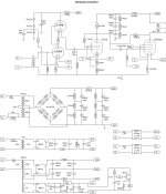
The transformer is a standard, center-tapped push-pull, with UL taps at 40%.
Driven by a pair of the GU80. I ordered the transformer in a somewhat "standard" configuration, so as to preserve the investment - just in case that I need to fall back to some "typical" PP UL technology within a different project (after abandoning this one).
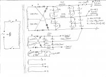
Indeed, I did not have the opportunity or stamina: neither to practically test the anode at 3kV, nor the S3 at 2,4kV. But I *did* test the anode at up to 1,7kV, with a current limiting resistor on the S3 from the 40%UL tap, with DC also at 1,7kV.
Indeed, without the current limiting resistor, the S3 gets red and may disintegrate under unfavorable conditions. I use 1k/20W resistor on the S3 to limit the amount of power dissipated upon it. Indeed, it *was* an issue. Thank goodness that I had the common sense to use a variac and see how things evolve as I gradually increased the anode subsystem voltage. Almost blew the S3, but noticed the problem just in time.
Driven by a pair of the GU80. I ordered the transformer in a somewhat "standard" configuration, so as to preserve the investment - just in case that I need to fall back to some "typical" PP UL technology within a different project (after abandoning this one).
Indeed, I did not have the opportunity or stamina: neither to practically test the anode at 3kV, nor the S3 at 2,4kV. But I *did* test the anode at up to 1,7kV, with a current limiting resistor on the S3 from the 40%UL tap, with DC also at 1,7kV.
Indeed, without the current limiting resistor, the S3 gets red and may disintegrate under unfavorable conditions. I use 1k/20W resistor on the S3 to limit the amount of power dissipated upon it. Indeed, it *was* an issue. Thank goodness that I had the common sense to use a variac and see how things evolve as I gradually increased the anode subsystem voltage. Almost blew the S3, but noticed the problem just in time.
The distance in milimeters between S1 and S2 is quite small ... something like 2mm or maybe 1,5mm. On the other hand, you have a healthy 4mm or more between S2 and S3 ... Compare this to 5mm between S3 and Anode.The screen grid is rated for 600V, so I do not see how the suppressor grid can handle 2.4kV...
Normally, S3 would be in pentode mode and "grounded" to the cathode.
The pdf implies that the tube can handle up to 3kV under derated power conditions. Simple proportion: 5mm - 3kV. 4mm - 2,4 kV. Just a guess.
Please kindly note that the S1 control grid may be exposed to very significant negative bias, even up to -300V. Considering the 2mm between S1 and S2 (at max. 600V) ... it is intuitively easy to understand why they imposed a +600V upper limit on the S2. ( 300+600=900V; 900V / 1,5mm = 0,6kV ...)
Cute feedback mechanism ..Nice schematic.")
Ok, that makes sense... so with the grid stopper on G3, you can drive it to full power? I am still wondering how much power the G3 can take.The distance in milimeters between S1 and S2 is quite small ... something like 2mm or maybe 1,5mm. On the other hand, you have a healthy 4mm or more between S2 and S3 ... Compare this to 5mm between S3 and Anode.
I dunno. To "full power": the G3 or the whole tube?Ok, that makes sense... so with the grid stopper on G3, you can drive it to full power? I am still wondering how much power the G3 can take.
Not that far yet. Work in progress. Need to design/create/fiddle with the preamp in order to test that. As long as the G3 is not glowing red, I think I feel comfortable. In the future will need to test it with some lower valued resistor and see at what value it starts glowing. Then add some 30% more ohms for margin and be done with it. Currently those are 1K / 20W. The resistor is probably "oversized" in terms of wattage. Just wanted to be better safe than sorry.
The "how much power the G3 can take" question - I see a possible empirical test for that. Just throw in a variac and start gently going up with the volts on the Anode Supply subsystem, with a relatively small G3 resistor, say 47ohms, and see if and when it starts glowing. Then just test the voltage drop on the 47R and we get a representation of the G3 current.
But the G3 current is only a part of the story, I think. The "main" stream of electrons going to the anode is bombarding this G3 ... would it not partially heat up from that bombardment too ? (i.e. as a partial function of the anode current?)
Besides, if the anode is bright red, ... it radiates into the insides, and radiatively heats up the G3, which then has a lesser breathing room for self-heat-up from it's own G3 current draw ... Might prove to be more complex than initially anticipated. I will stick with the conservative 1kohm for the time being.
Just as a pure "practicality" - I just simply do not feel comfortable with the tube's anode glowing brighter than medium orange/red, which is equivalent to 1400V * 250mA Cathode current = 350W. Not that it can not handle more. It can, but I just do not think comfortable with all that radiated heat and all. The medium orange / red is sexy enough in terms of the looks, the electricity bill will be stressed out a bit anyway, and as for the "music" power - more than I will ever need, in terms of normal living room conditions. Besides, the 350W is just about the max. that you can reasonably get away with, not using any forced cooling, fans or stuff, and not char-coal the wooden chassis. Besides, two tubes pushing and pulling in each monoblock, that becomes a whopping 700W on those anodes, add to that the 300W on the filaments. And that is per each monoblock. Practicality may force me do go down on the current to say 200mA or even lower.drive it to full power?
Last edited:
Sounds "scary" - but with a variac, it actually might be a very good idea ...Since there is no data given for G3, the only way to find out is to run some tests yourself, you can disconnect the anode, so G3 becomes the anode and gradually increase the grid drive to see what power you can get out of it.
Hy zjjwwa !
Not sure did you want to made SE or PP amp with those GU80 tubes , but for HI -FI audio use go with PP/AB class with 1,2KV B+ and 0,6KV for G2+ and G3 tied on the ground line .
In this configuration you can easy get that 0,6KV G2 voltage from HV secondary coil CT on main transf.
BTW , friend of mine successfully use four GU81M for his PP mid-fi hi power AM/MW modulator , pentode connected and with around 3KV for B+ .
Best Regards !
Hello!Hy zjjwwa !
Not sure did you want to made SE or PP amp with those GU80 tubes , but for HI -FI audio use go with PP/AB class with 1,2KV B+ and 0,6KV for G2+ and G3 tied on the ground line .
In this configuration you can easy get that 0,6KV G2 voltage from HV secondary coil CT on main transf.
BTW , friend of mine successfully use four GU81M for his PP mid-fi hi power AM/MW modulator , pentode connected and with around 3KV for B+ .
Best Regards !
Looked at the tubes - they are actually labeled "GU-81". Whatever.
Yes, I am making a PP amp. Monoblocks. But not going AB. Just plain A.
Do not need that much power in my living room. But I like the quality of the "class A" sound. Yes, I did actually try the "traditional pentode" topology - it works quite good. But I like this thing that I came up with somewhat better. Maybe it will degrade with high values of peak-to-peak driving signal, but for small signal it sounds simply better, for my ears. And the gain of the tubes is much higher, potentially allowing for an almost "single stage" amplifier. This alone has it's sonic benefits. The "three-elements-in-signal-path" approach.
When G3 tied to ground, the amplification factor of the tube reverts to "normal" - as per published specifications. In such a configuration, both the currents and the output signal swing are much much lower.
Thanks for your inputs!
That configuration you mention is my "Plan B" if this weird topology of my goes down the gutter when tested with big signal swings. But for "normal pentode mode" - I would need to build a "whole preamplifier". If possible, I would like to skip that.
Cheers,
Ziggy.
Since you do not need the power, a backup option could be "enhanced" triode, tie G3 to the cathode as usual, and tie G1 & G2 together as the input, I think this should be safer than trying to get more power with G3 UL.Hello!
But not going AB. Just plain A.
Do not need that much power in my living room. But I like the quality of the "class A" sound.
Ziggy.
Hello!
Looked at the tubes - they are actually labeled "GU-81". Whatever.
Yes, I am making a PP amp. Monoblocks. But not going AB. Just plain A.
Do not need that much power in my living room. But I like the quality of the "class A" sound. Yes, I did actually try the "traditional pentode" topology - it works quite good. But I like this thing that I came up with somewhat better. Maybe it will degrade with high values of peak-to-peak driving signal, but for small signal it sounds simply better, for my ears. And the gain of the tubes is much higher, potentially allowing for an almost "single stage" amplifier. This alone has it's sonic benefits. The "three-elements-in-signal-path" approach.
When G3 tied to ground, the amplification factor of the tube reverts to "normal" - as per published specifications. In such a configuration, both the currents and the output signal swing are much much lower.
Thanks for your inputs!
That configuration you mention is my "Plan B" if this weird topology of my goes down the gutter when tested with big signal swings. But for "normal pentode mode" - I would need to build a "whole preamplifier". If possible, I would like to skip that.
Cheers,
Ziggy.
Ziggy
-Yes that was my thought to , to make Hi quality sounding (Ab) class not (aB) class PP pentode connected OPS , where A class region of PP- OPS operation will be maximum extended before OPS enter in B class region of operation .
-Found that best compromise between many factors for those Russian RF power pentodes and used for A class of operation is when B+ G2 x 2 = B+Anode , for example , GU13(813)- B+G2 =0,75KV x 2=1,5KVB+A , GK71- B+G2=0,4KV x 2 = 0,8KV B+A , GU81M -B+G2=0,6KV x 2 =1,2KV B+A , .... and of course always with G3 tied to ground line .
-Further I will strongly suggest to you to go with DC coupled CF driver stages , bipolar supplied , and I think that standard EL84(2x) tube triode connected can do the nice job , in this context check schematic from that old Philips EL6471 - 1KW amp , If I remember correctly there two EL34 drives two tetrode QB3,5/750 DC coupled .
- If you need I can draw you quick concept schematic .
Last edited:
Yes, that sounds interesting. Are you saying that a single EL34 used as CF (resistor loaded??) to drive each single GU-81, or are you talking about some "push=pull" driver stage ? ... Mentioning Push-Pull, what do you think about a mu-follower, or maybe an SRPP driver stage, configured from a pair of mid-powered tubes, such as EL34 ? Overkill ?-Further I will strongly suggest to you to go with DC coupled CF driver stages , bipolar supplied , and I think that standard EL84(2x) tube triode connected can do the nice job , in this context check schematic from that old Philips EL6471 - 1KW amp , If I remember correctly there two EL34 drives two tetrode QB3,5/750 DC coupled .
- If you need I can draw you quick concept schematic .
If you could drop me a draft drawing of your concept - I would be very much obliged. (Yes, Please!).
Cheers,
Ziggy.
Intriguing. Also an interesting concept. Yes, I think I like the it and I will need to try to strap it up the next time around and see how it goes.Since you do not need the power, a backup option could be "enhanced" triode, tie G3 to the cathode as usual, and tie G1 & G2 together as the input, I think this should be safer than trying to get more power with G3 UL.
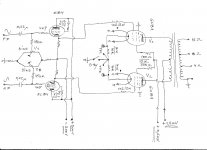
Very nice. Classical but nice. The Power supply is familiar. Similar to the one I have, slightly different configuration, but same topology. So you suggest to go for a dual symmetrical voltage feed for a simple Cathode Follower pair ?Here is the quick concept draw , BTW this concept also mean GNFB free Ab class PP amp to .
Hmmmm ..... I think I like it.
The more so that I have a few additional power transformer tappings which I could use for this ...
My OP Transformer is 6600 ohms (from anode to anode) .. into 8 / 4 ohms.How much power is expected ? What is the impedance of the OPT ?
Initially, I was hoping for some 100 Watts in pure class A (with a "classical" pentode topology, i.e. not naughty topology, which was the earlier version of my schematic that I posted). That would be the amount of power achieveable from the "A" characteristic - as derived straight from the pdf file and the anode characteristics graph.
But now .. now it is a slightly different story. Franky, with this "naughty" configuration that I am using lately - I do not know "what" to expect. With the S3 UL approach, the amplification factor changed significantly and the "new" characteristics are utterly unknown to me, apart from a few point to point measurements I made.
I am hoping that with the "new topology" and with the same 6600 ohm OPT I will get a similar 100 W of class A output, albeit with a much higher input signal sensitivity.
Whatever it will be - it will be more than I will ever need. For home use, at least.
- Home
- Amplifiers
- Tubes / Valves
- GU-81m tube amp schematics???