I don't have created models for them. I have created a bunch of symbols only, for my sketches.
The op-amps are in another topic and manuals online. Most people do not care to use them due to complexity but having used many IC op amps and finding them so useful I like the idea.
Thanks for the models others have made though!
The op-amps are in another topic and manuals online. Most people do not care to use them due to complexity but having used many IC op amps and finding them so useful I like the idea.
Thanks for the models others have made though!
Attachments
Last edited:
...do you plan use GU-13 in Triode or pentode?
The preliminary tests I have done shows that UL gives best results.
(Used OPT was Hammond 1628 SEA)
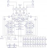
This is the schematic of my GU80 PP that I have built on my kitchen table, started up and did some preliminary tests / listening sessions.
Your comments / Critique - kindly Welcome.
This circuit actually works "as is". No preamplifier is necessary. No volume control necessary. Straight from the CD RCA output jacks, the SPL level in normal room conditions is actually already quite ... satisfying.
It is my own creation, based on several rounds of trial and error (some - explosive).
Jumping ahead of your very very first question:
I do not know how to name this topology.
I think that the tube itself is in some sort of "tetrodish" mode.
I think that the topology, in a nutshell, would be something like:
"A Hybrid_Horizontal_Vertical_UltraPath, with
Suppressor Grid HV_Ultra_Linear, with
Screen_Grid_Negative_Feedback and
Power_PTC_Squared_Autobias ... "
For small signals - it works. Quite good, actually.
I am not sure how it will behave when exposed to big signal swings on the input.
Ah, yes, I did try various forms of negative feedback, but came to the conclusion that it sounds best with neither voltage, nor cathode current negative feedback.
If I am at risk of some sort of danger, when applying a large signal to the input, please let me know.
It also works quite well with coupling capacitors. For the time being, I was using a 1:3 step-up interstage transformer.
If you see any room for improvement, please share your thoughts with me.
Best Regards,
Ziggy.
{{ EDIT: The voltages on the schematic are the ACTUAL measured voltages under LOAD condition. The raw unloaded supply voltages are something like 1700V Anode, and 850V Screen Grid. }}
Attachments
Last edited:
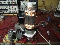
Films / photos of work in progress ...
Some links to films / photos of my work in progress ..
Please advise: do these open up correctly / activate as intented ?
https://www.facebook.com/video.php?v=894508577259848&set=vb.100001021436939&type=2
https://www.facebook.com/video.php?v=894498220594217&set=vb.100001021436939&type=2
https://www.facebook.com/video.php?v=894502610593778&set=vb.100001021436939&type=2
https://www.facebook.com/video.php?v=894507173926655&set=vb.100001021436939&type=2
https://fbcdn-vthumb-a.akamaihd.net/hvthumb-ak-xat1/v/t15.0-10/p128x128/10897249_896988757011830_896988527011853_54659_686_b.jpg?oh=ab2b31959ecc8a3467125ba4a5381375&oe=55E055D9&__gda__=1436304933_168c06a0578be6d9af4f937d04f343de
https://www.facebook.com/zygmunt.jerzynski/photos
The reason for this is because the S2 has a fairly low maximum voltage limit, at 600V referenced to cathode. Therefore, I started experimenting with the S3 as a possible candidate for the high voltage Ultra-Linear feedback signal.Suppressor Grid HV_Ultra_Linear
This one may not be obvious at first glance. My reasoning is as follows: The S2 is at a fixed voltage potential, but referenced to ground. On the other hand, the cathode is auto-biased, hence is jumping "up-and-down" with the signal swings.Screen_Grid_Negative_Feedback
This corresponds to the S2-to-Cathode voltage jumping "down-and-up". This imho constitutes a local ac feedback mechanism, as the more the tube conducts, the less S2-to-Cathode voltage there is to empower such conduction.
This one may not be obvious at first glance. My reasoning is as follows: The S2 is at a fixed voltage potential, but referenced to ground. On the other hand, the cathode is auto-biased, hence is jumping "up-and-down" with the signal swings.
How does the cathodes jump up-and-down if they are bypassed? Is the GNDANALOG not the same potential as the power supply ground? And what is the maximum suppressor voltage rating for the tube? I can't seem to find it in the datasheets... Also what is the UL tap % that you used for the supressor grid?
Yes, the GNDANALOG is the same potential as the power supply ground.
Maybe you are right. I will need to get rid of those "simple-bypasses" to ground. They are counter productive.
The most important bit for me is the "horizontal-ultra-path" which is the capacitor bank that is connected between cathode and cathode of the two tubes. Initially, I was thinking of a "classical ultra-path", meaning the "vertical" one, spanning from individual cathodes to B+.
At this point - thanks to a Mr. Jack Elliano, of a company called Electra-Print.com, for the conceptual inspiration that I found on his pages.
But, come to think about it ... it is very difficult and expensive to get some quality, foil based uF, rated at 1500V or 1600V.
So I started wondering ... What if I do a "horizontal-ultra-path" instead ?
Between the cathodes. As one of the tubes conducts more, the other conducts less ... hence the AC Current / Signal flows from Cathode to Cathode, and not from Cathodes to Ground, hence totally eliminating the power supply from the signal path. Therefore, the "simple-bypass" capacitors to ground, which I initially thought of as a safety means to eliminate any bad influence of the highly nonlinear light bulbs .... these are totally useless, if not even counter productive. Ihmo. Will need to throw them out and see where it goes from there.
Be easy on me, as I am but a humble beginner....what is the maximum suppressor voltage rating for the tube? I can't seem to find it in the datasheets... Also what is the UL tap % that you used for the supressor grid?
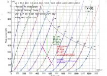
I came to a belief, that the minimum voltage on S3 can be as low as -200V, and as high as the Anode voltage. The -200V is actually documented as "possible" on one of the graphs in the tubes documentation. The "Anode voltage" limit is derived by means of a measuring tape. Scaled in milimeters.
After equipping myself with a six-pack of beer and a measuring tape, I established rough (non-tube-destructive) estimates as to the amount of milimeters between:
Anode -- S3; (5mm?)
S3 -- S2; (4mm?)
S2 -- S1; (2mm?)
S1 -- Cathode. (1mm?)
Based on these estimates, and on the six-pack, I made the following observation:
3kV / 5mm = 0,6kV/mm
")
The amount of mm between Anode (at say, 3kV?) and S3 (say, classical-pentode mode, wired to Cathode?) is just a tad bigger than the distance between S3 and S2. Therefore, if the shall be held at a fixed DC potential equal to 600V relative ground ... the voltage difference between S2 and S3 should withstand the full value of the anode voltage (3kV - 0,6kV = 2,4kV. 2,4kV/4mm = 0,6kV).
This may seem slightly irrational, but I actually tested it and it holds. Works. Does NOT arc over.
At least not at the 1,5kV anode voltage levels that I am using. One thing to watch out for though: The S3-helper-anode is much more fragile than the true anode. The S3-helper-anode has this natural inclination to melt and evaporate and disintegrate, if you let it do so. Current limiting resistors - highly advisable.
The UL tapping .... hmmm ....
Last edited:
Unfortunately, as a beginner, I do not have the means, to knowledge, nor the measurment infrastructure to calculate, derive, or otherwise make an educated guess as to the optimal value of this %UL tapping. Comming from the premises, that if I order an expensive OPT, with UL tapping, and this project goes astray, then I would at least wish to have the possibility of reasonably reusing the OP Transformer in a different context / a different project, I chose to order a standard 40% UL tapping. Caveat: with the possibility to rearrange the jumpers and convert it to 60%, if I really "need to". The transformer is symmetrically wound on a split bobbin, so such a rewiring trick should actually be possible.Also what is the UL tap % that you used for the supressor grid?
My WA-Guess is that the optimal UL tapping for the context of using with S3 should be much higher. Maybe even 60%. Reasons for such guesswork are twofold:
a). The S3 grid is very far away from the cathode, from S1, and hence has a very weak influence upon them.
b). The S3 grid is very sparsely wound, and hence its influence on the electron stream is the more so weaker, as would be the case of the S2 grid, which is normally used in such a context.
I have not yet gathered the inner courage to re-strap the transfomer so as to test the 60% UL option, but it is on my to-do list. Maybe, some day ...
Please kindly take note that the somewhat crazy notion of connecting S3 to the anode potential (UL), instead of connecting it to the cathode, might be perceived as a somewhat non-standard application. The use of S3 as a "helper anode" or as an electron-stream-booster .. it essentially does just that. The tube goes crazy. Starts to conduct like hell. Goes into some hefty current. Take care when experimenting, as you will be definitely in harms way. The barreter bulbs at the cathode may prove to be a true life saver. They saved my back a couple of times.
The MU (amplification factor) of the tube ... changes. Diplomatically stated. Essentially, it goes bezerk. It becomes higher. Can't give you an exact figure though. A single stage amplifier hence becomes almost / palpably possible. Maybe "not quite a single stage", but almost. Just connect the schematic as depicted to a variable output CD player and drive your neighbours nuts. No preamp necessary for that. Tested it mono. It was LOUD.
As for the barreter bulb farm, I try to configure it in such a matrix, so as to keep the current in the whereabouts of 150mA ... 200mA ... 250mA but in any event ... not more than 450 Watts dissipated on the glass per tube (450W/1500V= 300mA).
To put it differently: dull orange is OK. Semi-Bright Orange - gives you the creeps, but still seems to be OK.
Bright-Orange going into Yellowish - cut the fuses and run like Hell.
Just a Beginner Fledglings thought.
All of the above stated are just loose impressions of a beginner, subject to your critique, scrutiny and corrections, if such prove necessary.
Just to be sure that I understand semantics correctly: Suppressor is S3, yes ?The maximum suppressor voltage rating for the tube?
Because if you are asking about screen grid (S2) then indeed, there EXISTS a fairly LOW voltage limit for that one. The maximum S2-Cathode voltage is 600V and it is not permissible to exceed that value.
Therefore, it is "not possible" to create a "standard" UL configuration with this tube, using standard OPT's and B+ voltages exceeding 600V.
It "could" be possible, if you have a totally separate UL symmetrical winding, independently of the primary symmetrical winding, and on top of that, a separate, low voltage S2 supply for that dedicated UL winding.... very complex.
That was the reason why I started fiddling with S3 ...
The screen grid is rated for 600V, so I do not see how the suppressor grid can handle 2.4kV... If you are using a transformer with center taps along the plate windings, then the UL tap would be 50%. In UL operation, both the plate and suppressor grid put out power, so be careful when you crank it up, see if the suppressor grid wire turns red...
- Home
- Amplifiers
- Tubes / Valves
- GU-81m tube amp schematics???