The choke worked like a charm. Now there is only a faint hiss, but no scratchy RF noise. The cure was a choke and connecting the grounding more similar to a Firstwatt F5. Thanks!
Any negative effect?

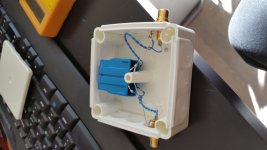
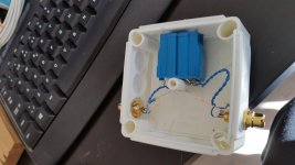
Here is a pic if you want to check my connections on the choke and the 3K9 resistor. The choke is called EPCOS - B82724J2142N1 - CHOKE, COMMON MODE, 2X27MH, 1.4A.
Datasheet: http://www.mouser.com/ds/2/400/b82724a_j-525424.pdf
The top par of pins on the choke goes to RCA ground on either connectors. The 3K9 resistor is connected to ground directly without a choke. The lower pairs of pins on the choke that is closest to the bottom of the box is for signal and source. Correct?
Attachments
Last edited:
Here is a pic if you want to check my connections on the choke and the 3K9 resistor. The choke is called EPCOS - B82724J2142N1 - CHOKE, COMMON MODE, 2X27MH, 1.4A.
Datasheet: http://www.mouser.com/ds/2/400/b82724a_j-525424.pdf
The top par of pins on the choke goes to RCA ground on either connectors. The 3K9 resistor is connected to ground directly without a choke. The lower pairs of pins on the choke that is closest to the bottom of the box is for signal and source. Correct?
Does it sound good?
I heard no difference in quality, but it was more quite without the computer RF noise. Just a little hiss, like the constant static from the power grid. Norway is known for noisy power but that is not so much of a problem. I must test it with both channels first, the other choke is ordered and will be here in a week.
To avoid adding a new thread I will tack my question on here:
I am building a stereo IRS2092 based amplifier and am trying to figure out the grounding. Here is my summary and let me know if it seems reasonable:
AC input ground - Connected to chasis of enclosure, this is the origin of my grounding point.
Meanwell 2 x 48VDC power supplies, I am wiring these in series for +/-48VDC (approved by manufacturer) so I connect V- of one supply and V+ of the other to ground along with the enclosure ground for each supply.
Speaker outputs I am going to ground the negative output of one amplifier and the positive of the other (with the input wired in reverse for this one). Doing this to allow bridging.
RCA inputs - I am planning to float these.
Microcontroller (Ardunio Uno) Including measurement circuits - Ground.
Does this seem reasonable?
Last edited:
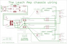
from the F5T Thread referring the the same diagram posted there by AJT
Post3.
Do not take any audio voltage references back to the PSU point where there are enormous charging pulses from the rectifiers. NEVER !
Speaker outputs I am going to ground the negative output of one amplifier and the positive of the other (with the input wired in reverse for this one). Doing this to allow bridging.
Fairly sure that this is going to be a problem. Most amp designs have the input and output grounds connected to the ground/0V. If you connect the live output of one channel to ground/0V you will create a short.
Specifically, you need the signal input to go to one amp's input, and also to a gain-of-1 inverting opamp whose output goes to the other amp. Then you will have a bridged output between the two amps' "hot" outputs.Fairly sure that this is going to be a problem. Most amp designs have the input and output grounds connected to the ground/0V. If you connect the live output of one channel to ground/0V you will create a short.
For bridged mode you do the phase inversion at the inputs to the amps, not at the outputs.
I'm baffled.
If you build a solid amplifier with a star 0V it will work flawlessly.
I've also got a pre-amp with a solid star 0V and it works flawlessly.
Connect the two together and you invariably end up with a loop.
I've got a commercial CD player which I'm not going to modify.
I thought breaking the loops in the pre might do the trick but it hasn't.
The question is where to break the loops.
Ground loops can be formed from more than the earth ground loop...
If you have two separate (left and right) line level interconnects that are not very, very close to each other all the way from one piece of equipment to the other, their ground shields can and will form a loop. Magnetic fields induce currents into this loop. If this is the case, I would try putting some small resistance (e.g. 4.7R) into one or both ground paths and moving the two cables as close together as possible.
Specifically, you need the signal input to go to one amp's input, and also to a gain-of-1 inverting opamp whose output goes to the other amp. Then you will have a bridged output between the two amps' "hot" outputs.
For bridged mode you do the phase inversion at the inputs to the amps, not at the outputs.
Invert one channel and you can use the amp as mono bridged or two channel with the speaker terminals of the inverted channel reversed.
This is HBRL & HBRR in the D.Joffe paper.Ground loops can be formed from more than the earth ground loop...
If you have two separate (left and right) line level interconnects that are not very, very close to each other all the way from one piece of equipment to the other, their ground shields can and will form a loop. Magnetic fields induce currents into this loop. If this is the case, I would try putting some small resistance (e.g. 4.7R) into one or both ground paths and moving the two cables as close together as possible.
But you must put the added resistance in the correct line.
The added resistance REDUCES the interference CURRENT in the loop.
For the critical Signal Return lead (coax screen) the interference current times the screen+connector resistance/impedance gives the interference voltage.
If one adds the resistance to that "screen+connector resistance" then one makes the interference voltage worse, instead of less.
- Status
- This old topic is closed. If you want to reopen this topic, contact a moderator using the "Report Post" button.
- Home
- Design & Build
- Construction Tips
- Ground Loops