Ok to powering the buffer from the gainclone PSU.
Yep, it can be done. However, it may have an audible effect on the overall amp (modulation products).
It is used with good effect on many valve buffered gainclones, as the differential voltage is 70V - enough for some tubes to operate.
Ok?
Owen
Yep, it can be done. However, it may have an audible effect on the overall amp (modulation products).
It is used with good effect on many valve buffered gainclones, as the differential voltage is 70V - enough for some tubes to operate.
Ok?
Owen
power from GC
<<modulation products>>
Would this be the case with 100, 470 or 1000mf caps after the zeners? Also, I'm rolling off the drivers at 12db/oct below about 85Hz, hence reducing energy demands on the GC PSU, would that make a difference? Seems strange, but I have not seen any reference to zeners being used for this purpose, is it considered an inferior method of adjusting the supply voltage?
thanks
Any news? Go get an opa 2132 or 4 , that chip you are using is unfamiliar to me, and is the only unknown....
Also, I'm starting to hate sockets... confirm good contact to pins with multimeter, had a couple of circuits which were otherwise driveing me nuts with no faults, just dieing, only to find its the damn socket not gripping nicely,
Also, I'm starting to hate sockets... confirm good contact to pins with multimeter, had a couple of circuits which were otherwise driveing me nuts with no faults, just dieing, only to find its the damn socket not gripping nicely,
Nordic said:Any news? Go get an opa 2132 or 4 , that chip you are using is unfamiliar to me, and is the only unknown....
Also, I'm starting to hate sockets... confirm good contact to pins with multimeter, had a couple of circuits which were otherwise driveing me nuts with no faults, just dieing, only to find its the damn socket not gripping nicely,
No news- I decided to refocus on the primary project (GC and speakers) and see if I could get those working, now that they are mostly, I'm looking at this again.
I checked the socket long ago. No problem there.
Possibly stupid question. The input and feedback resistors I'm using here are 47K ohms (not 47 or 4-point-7 k) and I'm just double-checking if that's correct or at least in the range. I've been looking at some other designs that indicate the NTE858 as an option (like the CMOY headphone amp ) and they seem to use much lower value feedback resistors. I understand that it's the ratio that sets the gain (and we want unity gain) but does the absolute value here also have a role to play, and if so, am I perhaps using too much resistance?
Dont worry, as long as they are the same, then you'll be fine...
The sockets I'd be checking are the 3.5mm mini-jacks. Is there any way you could test this without using the sockets (wire wrapping around the pins on the mini-jacks themselves..)?
They are the only things I can think of right now, aside from the voltage...
I've had a dig around, and I'll order a few bits, and see what I can send over.
Ok?
Owen
I can get audio through the jacks with the batteries unconnected, with a large volume drop due to the feedback resistor which is presumably the path the signal is taking. Twisting the pot raises and lowers the volume.
So unless someone can give me a good reason otherwise, I think that rules out a large number of potential problems with the basic input/output aspects.
Is there anything I could test with a DMM besides the voltages? I just hate working so much in the blind here.
I think what I am going to do is order some LF353s so we can take that variable out of the equation. For that matter I'll take the pot out too, just to make sure.
That sounds like a plan.
I'm dropping by my electronics emporium tonight on the way home to pick up the bits needed. It shouldnt take me long to get some images up, so you can see exactly what I've done. I really regret not having taken better pictures last time (and using a freebie web host )
)
My concern with the input/output, is yes, you may be getting a signal through, but it may be via the ground, and not the signal.
I'll build using mini-jacks (I'll test using my PC Speakers), and we'll see where I get to.
Ok?
Owen
I'm dropping by my electronics emporium tonight on the way home to pick up the bits needed. It shouldnt take me long to get some images up, so you can see exactly what I've done. I really regret not having taken better pictures last time (and using a freebie web host
)My concern with the input/output, is yes, you may be getting a signal through, but it may be via the ground, and not the signal.
I'll build using mini-jacks (I'll test using my PC Speakers), and we'll see where I get to.
Ok?
Owen
Owen,
If I swapped signal and ground wires, would that suitably test your hypothesis? I would think this circuit is simple enough that we ought to be able to debug it meaningfully without an o-scope.
Anything else to try?
My gainclone is in a steady state for the moment, so I am back to this project, refreshed with a little bit of success, and looking forward to seeing what it actually accomplishes.
Stereo jack plugs; A rule of thumb:
The Right channel is always at the Ring: I.e. Right = Ring (The plug’s configuration being: Tip, Ring, Sleeve).
The sleeve of course is always ground/shield: I.e. Sleeve = Shield.
That leaves the Left channel at the Tip.
from:
http://www.vandenhul.com/artpap/wiring14.htm
Try this. The one who must be obeyed put a clamp down in force tonight... I'll endeavor to get the bits tomorrow...
Ok?
Owen
Ok,
Parts .... check
Dodgy soldering iron .... check
spare wire .... check
Battery connectors .... check
3.5mm jack sockets from hell ... check
dual log 100k pot ... check
35 minutes... is that enough time...?
Batteries, you do have enough batteries dont you... GAAAAAAAAAAAAAaaaaaaaarrrrrrrrgggghhhhh..... FORGOT the *Batteries*
SO the upshot is, I have assembled a clone of you work.. the chip is a TI variation on the 353 scheme, but it uses the same pin numbering, and has very similar specifications. So hopefully tonight (if my speed soldering holds up) it should be playing sweeeeet muzak")
Owen
Parts .... check
Dodgy soldering iron .... check
spare wire .... check
Battery connectors .... check
3.5mm jack sockets from hell ... check
dual log 100k pot ... check
35 minutes... is that enough time...?
Batteries, you do have enough batteries dont you... GAAAAAAAAAAAAAaaaaaaaarrrrrrrrgggghhhhh..... FORGOT the *Batteries*
SO the upshot is, I have assembled a clone of you work.. the chip is a TI variation on the 353 scheme, but it uses the same pin numbering, and has very similar specifications. So hopefully tonight (if my speed soldering holds up) it should be playing sweeeeet muzak
Owen
Hi,
could some clever guy/gal make a video of this buffer assembly job and post it on you tube?
It would be far quiicker than posts 11 through 80.
Better still, does anyone live around the corner?
Pay him a visit and show him (with pointed finger) where all the bits go.
PS.demand a cup of tea or something stronger.
Well, it's assembled, and plays on both channels.
Those *stupid* 3.5mm jacks are a royal PITA - remember to wire them up on the unswitched output.
I also had 2 chips die from Static - something I've never had a problem with before, but, the guy in the shop did handle them quite a lot, and he was wearing the usual corporate uniform cacophany of man-made fibres.
So there's no worries with the circuit - but agreed on some-one local helping out.
Its the same story with any piece of silicon - the static gremlims will visit once in a while.
Oh yeah, and the track lifting pixies, and the none-wetting, wetting solder daemons.
It wouldnt be fun if it wasnt a challenge
Owen
Owen, any chance you could maybe put up a complete picture of the sucker, or email them to me and I can post them up somewhere?
I've verified, double-verified, and triple-verified the bloody jacks. I am probably a fool for thinking so, but I think that part can be ruled out as the issue. What I still wonder about is the power supply, and that's part of what I'd like to see in the pictures to make sure I have the exact wiring.
As for someone in the area, if there's anyone inside the Route 128 area of Boston, I would happily meet at a Starbucks or something and you could give it a look-over and tell me the completely stupid thing I've missed. I've done a bunch of continuity/resistance checks so i think my solder joints and tracks are good.
Hey-hey... You now need to send me an email with your address... so I can send you this sucker...
The gain isnt up to much, because the resistance (input and feedback) are low (120R each I believe), but it does have a dual gang 100K pot on it (carbon comp)..
I'll sort some pics out today or tomorrow (got to go to work now), so you can see what I've done
Ok?
Owen
The gain isnt up to much, because the resistance (input and feedback) are low (120R each I believe), but it does have a dual gang 100K pot on it (carbon comp)..
I'll sort some pics out today or tomorrow (got to go to work now), so you can see what I've done
Ok?
Owen
sansbury,
Can u re-post the schematic of the circuit u are assembling.
To know the connection of the 3.5 mm jack,
Insert the non wired jack into the non wired socket.
Open the jack cover and check the continuity from the tip, and note down.
Do the same for the next, body connection.
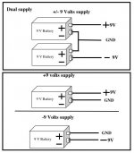
For battery connection refer drawing
Gajanan Phadte
Can u re-post the schematic of the circuit u are assembling.
To know the connection of the 3.5 mm jack,
Insert the non wired jack into the non wired socket.
Open the jack cover and check the continuity from the tip, and note down.
Do the same for the next, body connection.
For battery connection refer drawing
Gajanan Phadte
Attachments
OK, so just so you know how much this project has corrupted me, I am now sitting here in my kitchen with an oscilloscope. Things not working as well as possible, I can tolerate. Things I don't fully understand how they work, that's fine. But things that aren't working at all, and I have no idea why, now those drive me crazy.
Anyway, I haven't got my function generator yet so I've burned a CD with tracks with 5 minutes' worth of sine waves and square waves at 500Hz so I can test things. It was fun seeing that the wave output from my laptop soundcard is such noisy @#$! that a $9.95 CD player does better. The square wave is awful, more like a sawtooth, but the sine is very clean. Anyway...
With batteries and no load (i.e. headphones) connected, I can follow the signal all the way through the circuit. The amplitude and frequency are the same all the way through. I also picked up some LF353s to take that out of the equation. The circuit tests the same with the 353 as the 858, except that the 353 has an interesting notch which I'll put a scope shot of up later.
Anyway, where it gets interesting is that when I connect a load such as a pair of small earphones, the signal at the output goes bye-bye. Mucking with the voltage range and timebase gets me pretty much nothing.
For what it's worth, this @#$%!ed little circuit is going to cost me a good $200 in new gizmos before it's finished. Owen, I hope you're satisfied
Well, as you can see, my lack of comprehension knows no bounds I have a sort of sense of impedance, but I'm still wrapping my head around its implications and haven't quite gotten to it yet.
Are you saying that if I, for instance, hooked this up to the input on my gainclone, that it ought to work?
I have a sort of sense of impedance, but I'm still wrapping my head around its implications and haven't quite gotten to it yet.Are you saying that if I, for instance, hooked this up to the input on my gainclone, that it ought to work?
- Status
- This old topic is closed. If you want to reopen this topic, contact a moderator using the "Report Post" button.
- Home
- Amplifiers
- Chip Amps
- good and simple preamp for Gainclone