Nordic,
If you were to have a 3 way tone control, the mid having a sweep control as well, you can actually voice a system.
However, since the voicing and balance of bass/treble and the rest of the band has already been equalised in the studio, hi-end systems do not resort to such bells and whistles.
Yes, you would need a tone control for guitar cubes and other live music equipment.
Minion said:The Power supply I use has a Regulated +/-15v and unregulated +/-24v useing the LM317/337 regulator chips.....
The supply was originally designed for Mic preamps but I changed the design so I could Run a LM3886 Chip amp and a Opamp Based +/-15v preamp from it, I just removed the Phantom power circuit and I modified it so I could have More PSU filter caps and just took the Power off the PSU before the regulators but after the Filter caps for the Unregulated 24v rails.....
I have a PCB and stuffing guide for this PSU if you want it?? Let me know and I"ll post it for you.....
Possibly stupid question- I'm building one of the BrianGT kits and was looking at adding one of these buffered preamps as well:
http://myweb.tiscali.co.uk/nuukspot/decdun/gainclonepre.html
Like the previous poster, I'm wondering if I can double-purpose the PSU for the Gainclone itself. The preamp calls for LM317/337 regulators and an 18V PSU, while I was going to use a 25V transformer for the amp. The amp's PSU looks like this I believe:
http://www.chipamp.com/images/ps-rev3-sch.gif
Without having to reengineer the whole thing, is it possible to just siphon power off the transformer at 25V and feed that to the preamp and have the 317/337 chips regulate it down?
The toroid I'm looking at is the Avel 250VA 25V+25V seen on Parts Express which has dual secondaries. If I was going to tap power off of this for the preamp, would I use one pair of the secondaries for that, and another for the power amp, or would I want to do something different?
Thanks in advance!
Well the short answer is "Yes", (So is the long answer)......
You would probably have to add a Small PCB with the Regulator chips and a couple caps and resistors and just take a Lead from the Postive and negitive rails of your Gainclone PSU to the Regulator board and feed the Preamp from that.....
It would be a Bit too difficult to add the Regulators and related Parts to an allready existing PCB but you could build a seperate board for the regulators...
Or you could simply use a PSU that allready has Regulation for the Preamp....I could post the one I use for you if you wanted to etch your own PCB.....
Cheers
A 25 volt transformer will supply around 37 volts DC after the rectification. If you use the LM317/337 regs to drop that supply down to around 21 volts, you will need to use some pretty hefty heatsinks, and even then, those regs will get very hot! 
The other consideration here is sound quality (we are presumably talking hi-fi and not lo-fi). The preamp supply will be modulated by the demands of the power amp section. How much you will notice that depends on how good your system is and how critical you are with your listening.
However, given the cost of a small transformer and rectifier bridge etc, I honestly suggest building a separate supply for the pre amp section.")
The other consideration here is sound quality (we are presumably talking hi-fi and not lo-fi). The preamp supply will be modulated by the demands of the power amp section. How much you will notice that depends on how good your system is and how critical you are with your listening.
However, given the cost of a small transformer and rectifier bridge etc, I honestly suggest building a separate supply for the pre amp section.
owen said:Alternatively an interesting low current drawn op-amp buffer with a battery supply would do the trick - lots fewer componants, and easier to get 'right'. I've used OPA627, 637 and the venerable LF353 with great success in the past
Owen- any recommended designs you'd point to? I'm all for simple, as I can always go back and build something more intricate after I become more comfortable.
My Gainclone/buffer
http://www.freewebs.com/gaincloner/images/1-picture.gif
left hand side - LF353 buffer, right side LM3875 gainclone. Both inverting net phase shift = 0.
Piccies of its guts
http://www.freewebs.com/gaincloner/page5.html
Now this site has big pics behind the little ones - just click through if you have ADSL...
Alternatively
http://www.freewebs.com/gaincloner/
This is my normal site for those whose line speed isnt great. You still get a flavour of what's what though.
Have fun, and check out the LCC (Low Cost Case) - you should be able to make a nice box for less than £5 if you're careful in your scrounging
Owen
Owen, thanks for the link. A few more questions from the Stupid Club:
1. I'm building the gainclone dual-mono style. Do I need two preamp blocks, one for each channel?
2. Does it make any difference to the preamp if the gainclone is non-inverted? (OK, make that an *important* difference)
3. This page shows a bank of caps and a rectifier. I assume this is for use with a line PSU. If I do a pair of 9V batteries like you did, do I just wire the two batteries in series and feed the power straight to the op-amp chip?
4. Coming off a stereo plug (like an iPod or PC sound card), I have three outputs, right? Left, Right, and common. Which goes where on the schematci I linked above? Yeah, I know, DUH.
5. Any minimum recommendations for the resistors in terms of wattage?
6. The schematic is captioned, "Overall phase is non-inverting. Please remeber when wiring speaker outputs if whole circuit is used." It sounds slightly ominous, but aside from that I have no idea what it means.
Any answers greatly appreciated
A little capacitance won't hurt... I would still keep at least 10uf infront of the chip.. even with batery supply. You can get very good low esr caps in these low voltage ranges, for reasonably cheap (compared to larger values).
I experiment quite a lot with diffirent chipbased headphone amps, and in most cases I like at least 470uf to 1000uf at the battery, with 10uf closer to chip bypassed with 10nf at the pins themself. Any breakup in bass peaks will probably turn out to be too little capacitance on the big cap. However going too extreme on the value is also pointless and can have diffirent effects from makeing the opamp shrill to dull. With a good quality cap you fill see that less is more.
I experiment quite a lot with diffirent chipbased headphone amps, and in most cases I like at least 470uf to 1000uf at the battery, with 10uf closer to chip bypassed with 10nf at the pins themself. Any breakup in bass peaks will probably turn out to be too little capacitance on the big cap. However going too extreme on the value is also pointless and can have diffirent effects from makeing the opamp shrill to dull. With a good quality cap you fill see that less is more.
But does it blend?
(bump)
I tried building one of Owen's LF353-based preamps ( schematic here). Score so far is one smoked chip, and one not-really functional unit. Yay for cheap parts!
What I (tried to do) is to feed one channel from the line-out on a cheap CD player through the circuit and out to the cheap headphones, before I break anything more expensive. I get sound, but a lot less volume than I'd get if I just plugged the phones into the CD player, and interestingly, adjusting the pot seems to have no effect on the volume.
This leads me to think that the op-amp chip (using an NTE 858M) is doing nothing and all I'm getting is resistance which drops the level.
I checked for shorts and such and didn't find anything suspicious.
A few items which I haven't tried yet but am wondering about:
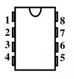
1. I'm not 100% clear on the inputs to the op-amp. The NTE 858 is a dual op-amp. Here is the pinout:
http://www.nteinc.com/specs/800to899/pdf/nte858m.pdf?page=3
I'm putting positive power to #8, negative to #4, signal in to #2, and getting signal out from #1. One thing I'm confused by is the schematic on Owen's site shows + and - inputs, but I don't know enough to relate that to this pinout with any certainty. His schema also shows one
2. The schematic shows tying the pot and one of the op-amp inputs to earth, but it's a battery-powered circuit, so do I need to find real earth, or can I just tie them to battery negative?
3. The cap that I have on the output is an elelctrolytic, but I'm not sure how it should be polarized, or if polarity matters in this application. I've tried it both ways, and it sounds/does the same either way.
I'm kind of stuck at this point as my testing tools are limited to a DMM and as you can tell my knowledge about what's going on underneath is a bit limited. Any and all advice greatly appreciated
(bump)
I tried building one of Owen's LF353-based preamps ( schematic here). Score so far is one smoked chip, and one not-really functional unit. Yay for cheap parts!
What I (tried to do) is to feed one channel from the line-out on a cheap CD player through the circuit and out to the cheap headphones, before I break anything more expensive. I get sound, but a lot less volume than I'd get if I just plugged the phones into the CD player, and interestingly, adjusting the pot seems to have no effect on the volume.
This leads me to think that the op-amp chip (using an NTE 858M) is doing nothing and all I'm getting is resistance which drops the level.
I checked for shorts and such and didn't find anything suspicious.
A few items which I haven't tried yet but am wondering about:
1. I'm not 100% clear on the inputs to the op-amp. The NTE 858 is a dual op-amp. Here is the pinout:
http://www.nteinc.com/specs/800to899/pdf/nte858m.pdf?page=3
I'm putting positive power to #8, negative to #4, signal in to #2, and getting signal out from #1. One thing I'm confused by is the schematic on Owen's site shows + and - inputs, but I don't know enough to relate that to this pinout with any certainty. His schema also shows one
2. The schematic shows tying the pot and one of the op-amp inputs to earth, but it's a battery-powered circuit, so do I need to find real earth, or can I just tie them to battery negative?
3. The cap that I have on the output is an elelctrolytic, but I'm not sure how it should be polarized, or if polarity matters in this application. I've tried it both ways, and it sounds/does the same either way.
I'm kind of stuck at this point as my testing tools are limited to a DMM and as you can tell my knowledge about what's going on underneath is a bit limited. Any and all advice greatly appreciated
Hey San, google time for you...
You need to search out some very basic opamp tutorials/overviews to understand the inverted and non inverted input on the chips... (as you call them + and -)....
Sadly you can't leave one input floating... I promise the first tut you spend 5 minutes with should clear this up for you... if you don't find anything, I'll look for you when I'm a bit more awake...
Sorry... googled and read a bunch of op-amp tutorials. I understand the idea a little better, but the sucker still doesn't work. I tried rigging up a true earth using the third pin on a 3-prong socket too.
At this point I'm thinking there are four possibilities:
1. I misread the schematic (it says inverting, and I hooked up to what I thought was the inverting input)
2. I'm misunderstanding the pinout on the chip
3. I've got a bad component or soldering job in there somewhere
4. I'm feeding the wrong signal through (I'm using 1/8" stereo jacks, and am using the one of the unique outs as the signal)
I'll confess to feeling a little frustrated at this point as there are only about 5 parts in here and I've gone through everything a number of times and I really have no idea what to do besides throw it in the trash and start over.
I will assume you made a small mistake, but lets see if we can narrow it down, on powering up, what voltage do you get between pin 4 and 8?
How are you shareing the chips, 1 per channel or 1 per stage?
do you have a small speaker you can use to confirm sound is comming through from the source?
Confirm pot wireing, input on full volume side, ground on min vol. side, output on wiper.
How are you shareing the chips, 1 per channel or 1 per stage?
do you have a small speaker you can use to confirm sound is comming through from the source?
Confirm pot wireing, input on full volume side, ground on min vol. side, output on wiper.
Nordic - thanks for the help!
I show 17.8V on 4 and 8.
Right now I have one channel only going through- figured I'd get left or right to work and then the other. I am testing using a pair of earbuds which I know work.
Audio is getting through, but at greatly reduced volume versus if I plugged them into the CD plater directly.
I decided to pull the pot out just to eliminate that as a possible source of error. I'm still not sure about the polarity of the capacitor though. I've tried reversing it with no discernible effects.
The ground part is weirding me out a little--do I need a true earth connection and if so, is there a way to test that I've got it right?
http://www.national.com/images/pf/LF353/00564917.pdf
You need to look at this PDF first, to be able to understand what I'm going to put next...
for channel 1 (using opamp A in the LF353 package)
the input is pin 2, and you will connect one 47k resistor in series (inline to that input).
You then need to connect pin 1 and pin 2 with a 47k resistor (the feed back loop, and the connection, must be after the input 47k resistor eg input-------resistor----connection----Pin2)
The output is from Pin1
Pin 3 must be connected to ground
for channel 2 (using opamp B in the LF353 package)
the input is pin 6, and you will connect one 47k resistor in series (inline to that input).
You then need to connect pin 6 and pin 7 with a 47k resistor (the feed back loop, and the connection, must be after the input 47k resistor eg input-------resistor----connection----Pin6)
The output is from Pin7
Pin 5 must be connected to ground
If you take a look at the datasheet
http://www.national.com/ds/LF/LF353.pdf
The maximum supply potential is 18V. Two brand spanking new 9V nominal batteries will exceed that value - an LED in series will drop about 3 volts, and keep you in the SOA of the chip (I probably got away with it by not having new fresh batteries - aided by my 2 children ).
The chip was supplied from a 12v SLA (13.2V nominal), the supply was initially designed for mains operation, but better results were had using a battery (singular)
I hope this helps
Owen
ps forgot to add, the buffer is inverting, when combined with an inverting gainclone, the absolute phase is 0 - ie its the same as the input signal, so the output of the chipamp should go to the red loudspeaker terminal Ok?
Ok?
Owen
You need to look at this PDF first, to be able to understand what I'm going to put next...
for channel 1 (using opamp A in the LF353 package)
the input is pin 2, and you will connect one 47k resistor in series (inline to that input).
You then need to connect pin 1 and pin 2 with a 47k resistor (the feed back loop, and the connection, must be after the input 47k resistor eg input-------resistor----connection----Pin2)
The output is from Pin1
Pin 3 must be connected to ground
for channel 2 (using opamp B in the LF353 package)
the input is pin 6, and you will connect one 47k resistor in series (inline to that input).
You then need to connect pin 6 and pin 7 with a 47k resistor (the feed back loop, and the connection, must be after the input 47k resistor eg input-------resistor----connection----Pin6)
The output is from Pin7
Pin 5 must be connected to ground
If you take a look at the datasheet
http://www.national.com/ds/LF/LF353.pdf
The maximum supply potential is 18V. Two brand spanking new 9V nominal batteries will exceed that value - an LED in series will drop about 3 volts, and keep you in the SOA of the chip (I probably got away with it by not having new fresh batteries - aided by my 2 children
).The chip was supplied from a 12v SLA (13.2V nominal), the supply was initially designed for mains operation, but better results were had using a battery (singular)
I hope this helps
Owen
ps forgot to add, the buffer is inverting, when combined with an inverting gainclone, the absolute phase is 0 - ie its the same as the input signal, so the output of the chipamp should go to the red loudspeaker terminal
Ok?Owen
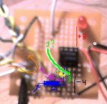
Unfortunately I have not yet achieved success... I started from scratch on a new board. I've attached a picture below, marked up to make things more visually obvious.
Numbers correspond to pin numbers. Black is battery negative, red is positive. The LED seen above the number 8 does not light, but I measure ~17V across pins 4 and 8 so I assume this is not the problem, though I will confess to some curiosity.
Blue 2 is signal in. I'm using 1/8" stereo jacks which I've taken signal left, signal right, and the common wire in from. The little blue arrow is one of the two coming in. The resistor goes straight across. I am building on stripboard with copper conductors that run vertically like the lines for 4 and 8. The Yellow 1 represents the feedback resistor that bridges from one to 2. Both resistors are 1/2W 47K ohm. The picture is poor but should show the physical layout properly.
Below the yellow 1 is a violet capacitor symbol followed by an arrow representing signal out. This is a 2.2uf polarized electrolytic. I've tried swapping the polarity but it seems to make no difference. This goes to another 1/8" jack which I have a set of earbuds plugged into.
There is an orange loop to the left of the violet arrow, representing the common input coming off the audio source. This comes in and goes right back out to the output jack.
Last there is the green 3 which is supposed to be our ground/non-inverting input on pin 3. I have this connected to a short wire which I have tried connecting to everything on the board trying to get it to work. What represents earth in this circuit is honestly the one part that I know I don't understand. Based on what op-amps do I would think this would be the orange common input but that didn't work, so I tried battery negative, and then actual earth, by rigging a source from an extension cord. Obviously, none of these worked.
If it matters, I am using the NTE858 chip which the shop told me was an equivalent for the LF353. The case says NTE858M and LF061E on it.
Attachments
- Status
- This old topic is closed. If you want to reopen this topic, contact a moderator using the "Report Post" button.
- Home
- Amplifiers
- Chip Amps
- good and simple preamp for Gainclone