Ok,
The resistors are fine only if pin 1 is the green pad ... ok?
I've looked at you image, and like the logical flow from L-R
Now the one error that is imediately apparent, the + should go to pin 8, the purple pad, and the - should go to pin 4, the red pad.
You should then be set to rock
It's great to see a work in progress !
Owen
Notch on the IC should match with the notch on the IC base.
Correct!, but in this case, we should be able to get what he has built so far working, and we can clock that one up to 'learning' for next time, 'cos there will be a next time
Owen
Another day, another pile of soldered insults
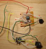
Well as usual, it still doesn't work, but I have more pictures, and this time bigger! This one shows the whole bloody mess except for the battery stack, but I think we can rule that part out.
Anyway, I've labeled everything in the picture, which I hope shows everything I did, including the alignment of the IC.
One stupid thing I did was to change the colors when I wired the pot, since I thought of a better mnemonic (gReen = Right, yeLLow = Left) than when I soldered the jacks originally. This is another thing to fix once I actually get it to work.
Right now there are four things that stick out.
1. Without the chip in the socket, voltage from pin 8->4 measures 16V. With the chip in, it's ~5.7V. I don't know if this is significant or not.
2. I am still confused as to which power leads belong where. Right now, I have two batteries in series, one with a +V end (red), one with a -V end (black), and one in between the two in series (green). The green wire is left floating as it wasn't clear whether it was used, but I brought it out just in case. All BS aside, I just need to know which leads need to go where!
3. I was a little uncertain about the jack wiring; I looked it up on Google and I think I have it correct
4. I have a stereo pot; At first I soldered the two pins together, but I looked at the schematic again and snipped them apart.
Anyway, I hope the attached picture provides sufficient amusement. I'm not giving up on this @#$! thing until it works!
Attachments
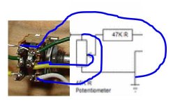
The pot is wrong.
It looks like you've shorted numbers 7 and 8 on the pot. dont.
You've shorted the input signal to ground.
Remove wire 4, 5 and 6 completeley. They're not needed
Wire 7 should be incoming ground. This should also run to the pcb. So connect on Neutral of the jack, then to to the pot where it is now and then on the pcb where 5 is.
Wire 8 is your signal wire out of the pot, going to the pcb. It should go where wire 6 is on the pcb.
Wire 9 should be incoming signal. Leave as is.
As usual please correct me if wrong.
If you've got your audio connectors right then it should work.
P.S Check your soldering and if possible post a pic after the changes. Please, one of the solder side too so we can check for shorts between the tracks.
If you've got new battaries please use them. the voltage should not drop like that.
P.S Check your soldering and if possible post a pic after the changes. Please, one of the solder side too so we can check for shorts between the tracks.
If you've got new battaries please use them. the voltage should not drop like that.
I want you to build EXACTLY what I showed you, use just one battery.
The drawing of the board and pot is with the pins pointed down, I just made 2 pots to illustrate the wireing
You should see a total of 4 groups of wires going to your board
Battery clip leads
RED - wire V+ to pin 8
BLACK - wire 0V to pin 4
Output socket's wires
Out GND - connect to a point on the gnd rail I showed you how to make with wire under the pcb... (the red lines are wire connections) (dont miss the connection for the IC pins that should connect to it too) other end of the out gnd wire goes to out socket ground
OUT L/R - one side connects to output socket other side connects to the free leg on the output cap (or pin 1 and 7 if you skipped those caps - can let DC through)
Input socket's wires
Input Gnd - connect to other end of the red ground rail in the centre.
Input L/R - to pins 3 of the pot.... (seen with pins pointed down and pot spindle pointed at you).
POT
connect pins 1 to the point on the RED GROUND RAIL in the centre where you connected input socket GND wire.
Connect pins 2 to the free legs of the resistors connected to pins 2 and 6).
You can use some audio cable for connecting the pot, to shield inputs a little..... connect the two core wires to pins 2. Tie the pins1 together to form an audio gnd star and connect the shield of the wire to that...
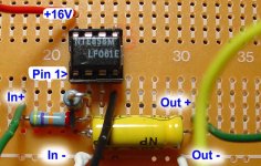
owen said:The board looks good. Power is being correctly applied to it, as are the signal in and out.
We just need to resolve the connections and the potentiometer now, and your prototype should be up and running.
Nope still nothing

Pots were rewired according to instructions. Jacks were rewired also.
Checked and I have 16V across 8 and 4 so batteries doing their job.
Everything checked for solder shorts.
According to Owen the rest looked OK, but it still doesn't do anything but sit there and laugh at me.
So I tried adding the Ground rail specified by Nordic, which does not appear in Owen's schematic. Though I maybe didn't get it right since it makes no sense to me. It's just a couple of wires to various points on the circuit being tied together, right? Because there's no other way to physically do it that I can tell. I tied all the points together using a common track on the board, and nothing changed, as usual.
Oh, and I tired swapping in a fresh IC, just in case I thoroughly fried the last one, two, and three I put in here.
I am getting used to soldering and clipping for 45 minutes, connecting power, and having nothing happen. If sound were to miraculously emerge, I might collapse from utter shock.
I'd send a picture, but my camera's hiding from me. At this point the only reason I'm still at it is that after all that you guys have put in trying to help, I'd feel bad giving up.
Are there any oddball problems we're not considering here? Even by my own personal standards this is getting a little ridiculous and I'm starting to question my own ability to see straight. I can only imagine what you guys are thinking

Ok,
The main question I have is why the 3.5mm mini-jacks. This could well be the source (pardon the pun) of the current problem. I havent checked the connections for a mini-jack - the top collar is ground, the middle ring is right, and the tip is left, I think.
These connections should be checked again. If you're feeding the ground input into the opamp, then you'll hear nothing. Likewise, if you're feeding the signal into the ground, you'll also hear nothing.
If you'd like, you can send it to me, and I will try to resolve the remaining issues for you. I'll document them here, so folks can see what I have done to fix this up.
The absolute best thing is that now, you'll be quite good at soldering, and that is never a bad thing.
Owen
Sansbury,
I'm serious, if I can help to sort this out, them do contact me.
And dont worry about how you feel, many of us have been through worse.
I have no doubt that you can see, and you will look back on this in a positive light, but I can never understand why the first born are always the most painful (in my case 430V)
Owen
OK, so I decided the best thing to do was to break this down and start over, testing each point of error along the way.
I took the pot and the jacks apart, and soldered them back together, so I had a jack wired into the pot wired out to the other jack. I plugged the source in and verified that the pot would pass the signal to the other jack, and it did. So I think I can conclude these are wired correctly.
Next, I resoldered everything on a new board. I used all fresh parts. before plugging in the chip, I tested for continuity and shorts, and everything tested ok. Without batteries attached, I could get sound through--obviously at lower volume due to the ~96Kohm in the path.
Adding batteries of course did nothing. I tested and saw 16V across pins 4 and 8.
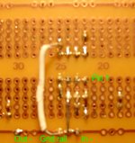
Anyway, here is the top. I put the ground on the bottom so you'll see that in the next picture.
PS. Also added a second LED to the power circuit to drop V down to 14.5V+, just in case as the data sheet said (I think) 15V maximum operating. No change of course.
I took the pot and the jacks apart, and soldered them back together, so I had a jack wired into the pot wired out to the other jack. I plugged the source in and verified that the pot would pass the signal to the other jack, and it did. So I think I can conclude these are wired correctly.
Next, I resoldered everything on a new board. I used all fresh parts. before plugging in the chip, I tested for continuity and shorts, and everything tested ok. Without batteries attached, I could get sound through--obviously at lower volume due to the ~96Kohm in the path.
Adding batteries of course did nothing. I tested and saw 16V across pins 4 and 8.
Anyway, here is the top. I put the ground on the bottom so you'll see that in the next picture.
PS. Also added a second LED to the power circuit to drop V down to 14.5V+, just in case as the data sheet said (I think) 15V maximum operating. No change of course.
Attachments
Derived power from GC PSU
Hello,
I recently posted a similar question regarding powering a buffer from the gainclone PSU, to which I received no replies, so I'll ask it here. Basically it's this. Why can't you drive the buffer from the GC supply (Audiosector premium 3875) dropping the voltage through 15V zeners, with a cap (100mf ?) immediately after the zeners, and the IC (OPA2134) de-coupled by 10mf tantalums paralleled with 100nf ceramics at the pins? And should the 100mf? cap be a Black Gate, or would, say, a Panasonic suffice?
With the chip in, it's ~5.7V.
Hadn't noticed this. In the national datasheet, the absolute minimum voltage is listed as 6V for the chip. (note 7 on page 3). It could quite well be that the chip is simply not 'turning on' because its supply is below the minimum. Tryt bypassing the LED (I know what I said before, but the supply sag should be enough to protect the chip, and your soldering is good (no nasty clangers visible), so it should be safe to do so.
Apply the power, with the chip in situ, and then measure the voltages between pin 4 and pin 8.
Could you publish them here.
My help is the least I can do - its my circuit
Owen
- Status
- This old topic is closed. If you want to reopen this topic, contact a moderator using the "Report Post" button.
- Home
- Amplifiers
- Chip Amps
- good and simple preamp for Gainclone