Krisfr - That's called "blundering", not engineering. Any type of engineering that I've ever been a part of, or know, would ALWAYS start with a very specific set of specs/goals.
Well I have made a decent living BLUNDERING along for a few years, and I will with the grace of GOD and the help of others here BLUNDER on with or with out your input, thought, philosophy of engineering, or other influences. IF you will kindly look at my post above and the post of others U will see that WE started with very specific goals and or thoughts.
We did not blurt out here build this exactly in the first post.
I got a 20 dollar bill that bets MORE DIY's will build this amp than what you are going for. And I got a 100 that says yours in not 100% perfect as you have reiterated.
THIS one will be tested and tried before we'll turn on the go to Group Buy Light!
We are not CLONERS we are INVENTING ENGINEERS!!!
Last edited:

This thread is hilarious and pointless!!! You guys do realize that this is NOT improving the Goldmund amp, but creating something else entirely? Right? If something new no longer resembles the original, then what is the purpose of this discussion?
May I kindly suggest:
Why don't you all agree on the specs, the cost, the topology (MOSFET/Bi Polar), etc. that you'd like the amplifier to have and then just build the circuit that will give those specs?
That's how real engineers do it")
We have a separate thread- so chill!! , I have basically the original in my CX (VAS cascode added) , I do know how it sounds. My CX 2 is just a superior version of it. I even tried it with MPSA 92/42's ... it works and out performs the original (stability / bandwidth /sourcing). The esoteric hype surrounding the original is nothing to write home about besides how much money you can spend. I hear these things through crude BJT EF2/3 OPS's , and they sound phenomenal , so with laterals I would almost bet my mother that they would satisfy the "picky".
I only offered an improvement , the original has limitations that can be minimized , but not eliminated ...
Salas was right to suggest a fully separate regulated supply w/ capacitance multiplier for the input/voltage stage.. it is surprising Goldmund did not refine the design to this point.
For all that $$$ , I would expect better.If it is demanded , I will simulate with the MPSA's, but the models for those devices are inferior to the KSA/C's(fairchild). If you would notice , all the "high order" designers who left this forum (syn08, Andy C. , GK), almost exclusively use the fairchild models for their PPM amps ... and with just cause.
I might use it for my BJT's , but porting it to laterals is actually easier than the BJT's (less partz).
OS
Last edited:
Are those KSA you use belonging to the low Rbb variety?
KSA1381 FBU and KSC3503 FBU, $0.34 apiece(mouser).They are higher Rbb , best used for voltage stages (300v). the Ksa992/ksc1845 are basically "clones" of the original japanese low noise small signal devices. I use these exclusively for cascodes / bjt input stages , VAS Ef's , etc. They exhibit very low noise when used as the LTP. (absolute silence). I have tried the fairchild J-K lineup for JFET'S(J201)... not bad -cheap, I can't hear anything !!
In general , as two groups of BjT devices working together ,they outperform MPSA-xx , BC-xx 2n-XXXX and are easier to source in N. america. Fairchild even has newer modern "clones" of the MPSA line (KSP92/42) , and of course they have the old MJE340/350.
OS
I want to give my 110% support for following Salas advice regarding powers supply mods.
This alone will make a significant improvement.
That is his forte.
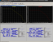
An interesting thing came up while simulating with the MPSA92/42's. Using the same input stage setup , 70mA bias at OPS , and 6ma standing current for VAS ,the high order harmonic content of the MPSA's VAS (I used KSP42/92 models - better) were VERY different from the Ksa1381/c3503's.
The first (attachment 1) is of the MPSA VAS. The thd was X 10 (.015+ %) the extra distortion was all in the 2'nd harmonic (H2).
The second (attachment 2) is of the More advanced CX. Equal H2 and 3 but both are far lower (.0006%).
Both tests were taken with 2.2mA tail current /1Khz / 40V p-p. The MPSA test was with the goldmund resistor arrangement at the VAS (no cascode).I also swapped Ksc1845's out for 2N-XXXX's , no difference with that cascode(input stage) . The input FET pair might be a factor in noise and total stage gain but should not affect the THD much (swapped that out , too).
My conclusion is that possibly a part of the the Goldmund's sound is the result of this dominant 2'nd harmonic distortion component. The lower distortion CX just has less of everything by a factor of 10. Nagsy suggested that we are deluded to run a test like this on a BJT output stage. THIS DOES NOT MATTER , A VAS will have it's own sound and characteristics regardless of what output stage one uses. What you hear on the speakers is a different story , the laterals are superior.
You can listen to a input/ voltage stage with headphones in pure class A. I am only simulating to discern what merits , if any... the Hitachi variant that guldmund uses is the "magic" behind the sound.
What we need now to round this off is someone who builds with laterals to give some input. (gatestoppers , layout , gate protection).
I was amazed at the differences a device can make , even in a simulation. We must choose what is best sonically, H2 swamping out higher order components or the absence of these components entirely .
OS
Attachments
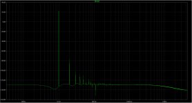
My version at 40V pk-pk into 8Ohm
Lateral OPS?? By all means , share it ..
Edit: (Below) my LTP/VAS all alone (taken from drivers-no OPS) .00008%
Them "Dirty BJT's" ... this would make for a killer pure class A creation.
OS
Attachments
Last edited:
Okay, I have been away and there has been plenty of activity. I had to make notes.
Firstly - no, it won't be the Goldmund. The members here have their own ideas of what will sound better, what will sound worse, some of us believe Nagys, others want a modified circuit.
I made this thread to satisfy a varied base of members who are interested in a modified design. I believe these people understand themselves what they risk on this adventure, which is why I want it to be a group effort.
Wishful thinking, in my opinion, helps no one. Knowing this, I don't want to give false hopes. My aim is to improve on the original design, which has been proven to sound good.
If we wanted to, I'm sure we could design from scratch an amp with much better specs. But it wouldn't be the Goldmund, and yet we hear the Goldmund is one of the best.
Even if we don't succeed, it will still be a great learning experience. And we will get to SEE how the new design falls short, and maybe do it right the second time. Is this worth it?
VAS Degeneration
We could remove the VAS degeneration, but this will have an extreme affect on all other aspects of the amp. The first post goes more in-depth about this.
Yes, OLG will increase, but OLG bandwidth will not. For example, look at the difference in OLG between the original and my mod. OLG and BW are totally separate. Open-loop gain increased at DC but the unity-gain frequency does not. So even if we improve bass or 1KHz performance, 20KHz performance will not be affected much as one poster pointed out, after simulating the amps at 20KHz rather than at 1KHz which was my test frequency.
So I would like to propose a new design criteria:
OLG -3db point should not go below 1KHz, which is the BW of the original.
I like the way Jam said it:
If we add enough OLG and dope the amp up on compensation, these problems are easy to ignore when looking at the other specs of the amp. However not only is this reported to sound bad, but it is a sign the amp is unreliable. The compensation necessary to sweep these issues "under the rug" is also disastrous for other areas of design that may be more important than blanket THD.
In this light the idea of making an amp perform well before adding feedback makes sense. It also makes for a more reliable design.
Third, some posts I've read seem to indicate that the FETs used are key to the good sonics. True, decreasing OLG will decrease the distortion contributed by the FETs, but it would seem that these distortions are mainly benign. I think we should use the same FETs, as these seem to be one of the keys to the original design. I think the high NFB route would be in favor of using other devices. Not sure about this, comments?
Current Mirror on input LTP
Wahab has given a good reason for this. My thoughts:
1: The CM transistors will have low Vce and thus high Cob.
2: One transistor will have widely varying Vce near its saturation point; this is made much worse by the VAS degeneration. This is bad for linearity.
3: The input to one VAS will be very high-gain and very high-impedance. This will increase the OLG of the amp by a crapload, and thus nearly it's entire phase/gain behavior will depend on the gain/phase behavior of the VAS Ib and the CM transistor, which will have high Cob and is operating at low Vce.
I oppose this.
Offset and VAS
Some posts were discussing the affect of degeneration on the balance of the input LTP.
The balance is controlled by the potentiometer connected with the 3k resistors at the top. If the FETs used are matched, then adjusting this resistor to 0 offset will result in a balanced LTP regardless of VAS balance.
I really like this, and it makes things simpler. However if the wiper disconnects, there might be problems. This will pull VAS current very high, probably destroying the FETs. This could partially be remedied by replacing R20 (in the original schematic) by a Vbe multiplier or diode of some sort.
Regulator Options
We could use different regs for the frontend and outputs. A shunt reg would work well for the frontend, and a cap multiplier like mine should do for the outputs, maybe? However all those FETs can draw a hell of a lot of power. It may be difficult to adapt my design, unless very large filter caps are used to absorb most of it.
BJT Outputs
I can help with this, but unless there is screaming and kicking, I'd like to stay on track for now. What do others think about using BJT outputs?
Full Wilson Mirror
I haven't tried this. I don't think the 4th transistor is necessary, a diode will do. Although I just simulated it with both and distortion wasn't affected at all. Could temperature tracking be a problem?
Regulator vs. C-multiplier
Don't ask me! Andrew, what's the difference?
The bass improves with the NPN version because the transistors use have higher gain, as is almost always true for NPN devices over PNP.
The design was to stretch the limits of the traditional C-multiplier. A design can only be as good as the parts that make it. This means if we extract the best performance out of two circuits using different parts, there MUST be differences.
I must also relay that this circuit has not been tested in real life. Real life testing may indicate other areas that need to be addressed.
- keantoken
Firstly - no, it won't be the Goldmund. The members here have their own ideas of what will sound better, what will sound worse, some of us believe Nagys, others want a modified circuit.
I made this thread to satisfy a varied base of members who are interested in a modified design. I believe these people understand themselves what they risk on this adventure, which is why I want it to be a group effort.
Wishful thinking, in my opinion, helps no one. Knowing this, I don't want to give false hopes. My aim is to improve on the original design, which has been proven to sound good.
If we wanted to, I'm sure we could design from scratch an amp with much better specs. But it wouldn't be the Goldmund, and yet we hear the Goldmund is one of the best.
Even if we don't succeed, it will still be a great learning experience. And we will get to SEE how the new design falls short, and maybe do it right the second time. Is this worth it?
VAS Degeneration
We could remove the VAS degeneration, but this will have an extreme affect on all other aspects of the amp. The first post goes more in-depth about this.
Yes, OLG will increase, but OLG bandwidth will not. For example, look at the difference in OLG between the original and my mod. OLG and BW are totally separate. Open-loop gain increased at DC but the unity-gain frequency does not. So even if we improve bass or 1KHz performance, 20KHz performance will not be affected much as one poster pointed out, after simulating the amps at 20KHz rather than at 1KHz which was my test frequency.
So I would like to propose a new design criteria:
OLG -3db point should not go below 1KHz, which is the BW of the original.
I like the way Jam said it:
Along this vein, those who read the first post know how I described the VAS degeneration resistors improving phase behavior of the amp. As the current flows through the transistors in series, the transistor with the lower transconductance or Gm (the ratio of Vbe change to collector current, which is nonlinear) will dominate the gain of the stage. This means that gain decreases at power peaks, especially at high frequencies where the FETs need a lot of drive. This nonlinearity of gain vs. current demand creates phase distortion. While no degeneration might look good at 1KHz, the amp's pulse behavior will be changed radically, and will be harder to control, because gain will not be constant with power; we may get it stable, but the phase margin will wander with output level.Obtain the required bandwidth (audio) before the application of feedback.
If we add enough OLG and dope the amp up on compensation, these problems are easy to ignore when looking at the other specs of the amp. However not only is this reported to sound bad, but it is a sign the amp is unreliable. The compensation necessary to sweep these issues "under the rug" is also disastrous for other areas of design that may be more important than blanket THD.
In this light the idea of making an amp perform well before adding feedback makes sense. It also makes for a more reliable design.
Third, some posts I've read seem to indicate that the FETs used are key to the good sonics. True, decreasing OLG will decrease the distortion contributed by the FETs, but it would seem that these distortions are mainly benign. I think we should use the same FETs, as these seem to be one of the keys to the original design. I think the high NFB route would be in favor of using other devices. Not sure about this, comments?
Current Mirror on input LTP
Wahab has given a good reason for this. My thoughts:
1: The CM transistors will have low Vce and thus high Cob.
2: One transistor will have widely varying Vce near its saturation point; this is made much worse by the VAS degeneration. This is bad for linearity.
3: The input to one VAS will be very high-gain and very high-impedance. This will increase the OLG of the amp by a crapload, and thus nearly it's entire phase/gain behavior will depend on the gain/phase behavior of the VAS Ib and the CM transistor, which will have high Cob and is operating at low Vce.
I oppose this.
Offset and VAS
Some posts were discussing the affect of degeneration on the balance of the input LTP.
The balance is controlled by the potentiometer connected with the 3k resistors at the top. If the FETs used are matched, then adjusting this resistor to 0 offset will result in a balanced LTP regardless of VAS balance.
I really like this, and it makes things simpler. However if the wiper disconnects, there might be problems. This will pull VAS current very high, probably destroying the FETs. This could partially be remedied by replacing R20 (in the original schematic) by a Vbe multiplier or diode of some sort.
Regulator Options
We could use different regs for the frontend and outputs. A shunt reg would work well for the frontend, and a cap multiplier like mine should do for the outputs, maybe? However all those FETs can draw a hell of a lot of power. It may be difficult to adapt my design, unless very large filter caps are used to absorb most of it.
BJT Outputs
I can help with this, but unless there is screaming and kicking, I'd like to stay on track for now. What do others think about using BJT outputs?
Full Wilson Mirror
I haven't tried this. I don't think the 4th transistor is necessary, a diode will do. Although I just simulated it with both and distortion wasn't affected at all. Could temperature tracking be a problem?
Regulator vs. C-multiplier
Don't ask me! Andrew, what's the difference?
The bass improves with the NPN version because the transistors use have higher gain, as is almost always true for NPN devices over PNP.
The design was to stretch the limits of the traditional C-multiplier. A design can only be as good as the parts that make it. This means if we extract the best performance out of two circuits using different parts, there MUST be differences.
I must also relay that this circuit has not been tested in real life. Real life testing may indicate other areas that need to be addressed.
- keantoken
Attachments
Last edited:
For the regs part talk of your essay, my recommendation is just add a good capacitance multiplier in line with the voltage stages rails. Few components, little dissipation, practical upgrade over nothing. Look for flat and open Zo. Your proposed circuit looks promising if scaled up for +/-110V and tested for no oscillations possible between the driver and pass. A reg is referenced and has a certain Vo target, a filter sags along. That is more natural subjectively in a power amp and tracks output sag. Feed from same Tx aux secondary winding. Stiff supplies sound err...stiff if not carried all along the whole amp. To reg up a whole heavy amp, its super structures series on Sat TV. Not the goal here.
So my regs would still be considered multipliers, even though they have over a 10 second response, lol. That could probably be decreased.
How much sag should we expect at the rails before the regulators at full power? This will determine how much voltage drop we should set for the regulators, determined by D1 and D3.
We can choose low voltage, high-current devices since Vce is designed to be as low as possible. Meanwhile, the FETs are hungry for many, many amps.
I will try to build those regulators soon, since they're easy. Of course I won't be able to test full power, but see if stability could be a major concern. They're also nice to have for my bench.
EDIT: for some reason I kept thinking "voltage stages" meant the output stage. This should make things much easier.
- keantoken
Last edited:
- Home
- Amplifiers
- Solid State
- Goldmund Mods, Improvements, Stability