I would expect there are a few reasons for omitting the source resistors.
I further suspect that the designers had considered very carefully how to get a resistorless design to work properly.
If we knew what was in their heads we could try to emulate their design.
I reckon the best we can do is guess and accept the risks involved with our guesses.
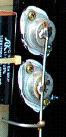
Or perhaps just because the source is connected to 'case' with those Hitachi TO3 mosfets.
Or because they are immune to thermal runaway and secondary breakdown.
/Hugo
Or perhaps just because the source is connected to 'case' with those Hitachi TO3 mosfets.
Or because they are immune to thermal runaway and secondary breakdown.
/Hugo
I don't know about electronics, but from what I read, and my observation on amplifier schematics, it is mainly because of the negative tempco.
About source connected to 'case', this has made me thinking, is it necessary to solder cables connecting the top casing of the mosfet like Conrad Johnson does ? I often do point-to-point so I have been tempted to do the same way, but it doesn't look pretty that way. I prefer a copper bar on topside of the mounting holes.
This might lower the possibility of oscillation...
Attachments
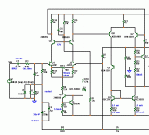
On the contrary, I was intrigued by ostripper's input/VAS stage...
But bipolar output? I think it will be 100% new design! And a completely different sound that can never be compared with the Goldmund.
And keep the emiter follower driving the gate of the mosfet.
The CXfet ?? this is what I would throw at a good set of laterals if I was rich enough.
 I know that it is stable , 700k bandwidth / 75v+/us slew , and I know what it sounds like (BJT's) ... below. easy to source, as well. (10$ board - complete)
You are right , the laterals would indeed make the CX "sing"...
OS
Attachments
Ostripper for President!
Jay,
I like the idea of bipolar outputs because the have more "crunch" for want of a better word. That being said I think Mosfets are ok, but I still have a preference for verticals. I think the topology is more important than the devices used in this instance.
I think that OS has a cool output stage that will work well in this application, if you consider his design an amazing amount of thought an innovation has gone into it. Clearly one of the best that has been offered in this forum.
Regards,
Jam
Last edited:
Jay,
I like the idea of bipolar outputs because the have more "crunch" for want of a better word. That being said I think Mosfets are ok, but I still have a preference for verticals.
I think that OS has a cool output stage that will work well in this application, if you consider his design an amazing amount of thought an innovation has gone into it. Clearly one of the best that has been offered in this forum.
Regards,
Jam
I still think the laterals would sound better. EF2's and 3's can be close , but only with an exceptional input/voltage stage. The 2sk134/j49 , being to-3's, have a unique sound which I believe is 90% of the goldmund's "magic" ..seeing what a "trainwreck" the original goldmund circuit is. A simulation of .03% (goldmund) compared to .001% (CX) is enough of a difference to be heard in the subtleties of soundstages. This also reflects the primitive nature of goldmund's implementation of the basic hitachi circuit. Having actually built the CX and "crippling it" by replacing the VAS cascode with a simple resistor to make it like the goldmund , I have actually a/b'ed these two variations (for real) in the circuit. I am sure the differences would also be apparent after "going through" the laterals , as well.
Edit: We are only relying on one mans opinion of what "the best sounding amplifier " is. My experience also involves the above TO-3 Hitachi lateral pair. In the 80's a similar amp was produced in kit form and surpassed the 8000$ genesis stealth in it's audio goodness. If I remember right ,it was exactly like the CXfet without the VAS cascode (goldmund like). The only difference was the remaining 4 VAS devices were running at over 20ma and driving the laterals (2 pairs) directly ... like a Otala design.
OS
Last edited:
hmmm ... maybe some tricks from bob cordell's book?
mlloyd1
mlloyd1
Simulation of both original (Goldmund_sim) and modified (Goldmund_sim_Kmods) schematic at 20kHz results in THD improvement by only 50% (from 0.02% to 0.01%). I fail to see how the 10 fold improvement seen by keantoken in the first post is possible.
Is there any interest on this thread of adding output transistors to the design to make 4 pair?
and to put places on the pcb for emitter resistors so they can be used or just jumpered out.
Will this be a board with a ground plane?
Will this board be tested and tested again by more than one person before going to a group buy?
Will some type of simulation that is verifiable be preformed?
Will NON exotic parts (as in obtainable with out mortgaging the house) be designed into the bom.
Will the overall design be "BLESSED" by at least 2 experienced, known & successful designers on the board as being at least Reasonable?
IF so I am in for 6 pairs...
Thanks
Jay wrote:
Hi Jay,
The links I posted are all for toroids - just to let you know. Yes, they might be expensive. I can see that Ostripper has a suggestion for a 500 VA transformer...
Karsten
Wow, that's very expensive! I think hammonds are EI transformers. EI transformers sound better imo. But noisy or induce more hum, unless special products are opted, may be.
I have enough transformers but the highest only 40Vac. Eight of them!
Thanks Karsten.
Hi Jay,
The links I posted are all for toroids - just to let you know. Yes, they might be expensive. I can see that Ostripper has a suggestion for a 500 VA transformer...
Karsten
... I'm here from "other " thread to offer my services , so we can , ofcourse to make an double sided , more compact .....PCB for better designed amplifier . I'm in standby from now .
Regards Alex.
Alex, YOU are the sane, absolutely relevant, needed and essential part of the equation that makes sense to have @ this confluence of the great minds....
There are not enough THANK YOU's to put in one post...
I look forward to some more of your exquisite EyE CandY.
I am acquiring the same program you use to create the Master Pieces.
Simulation of both original (Goldmund_sim) and modified (Goldmund_sim_Kmods) schematic at 20kHz results in THD improvement by only 50% (from 0.02% to 0.01%). I fail to see how the 10 fold improvement seen by keantoken in the first post is possible.
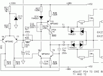
I wasn't comparing keen's 2 simulations , I was comparing his best Goldman to my best "symasym" type voltage stage (CX). it's a miracle what 1 more device will do for a circuit (20-30 fold at 1Khz). These are just simulations , but reflect the overall linearity of the circuit(s). The less to correct with global feedback , the better.
The second factor besides the total THD is the loading on the input pair and whether it is balanced or not. In the goldmund's case , the current mirror is "for show" and could be replaced with a diode. (below HH lateral design)
OS
Attachments
Last edited:
A small issue with the simulation schematic is that the original Goldmund schematic has a 2k7 series resistor in the driver voltage doubler. This will probably drop about 50 volts (assuming 20mA current). This would also imply that the +-80V supply suggested by nagysaudio is higher than what Goldmund originally has. Does not make sense to have lower voltage on the driver rails.
/Martti
/Martti
... I'm here from "other " thread to offer my services ............... I'm in standby from now .
Regards Alex.
makes it even more interesting

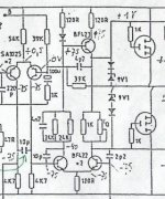
Here is LTspice schematic of Sentec ACM1 monoblock amp which was made in Sweden in the late 70s and early 80s. It was also sold as a kit. The topology is symmetrical but the driver and output stages are as in Goldmund. It has similar performance to Goldmund at least in simulation.

The actual schematic can also be found here:
Sentec-förstärkare, broschyrer mm
/Martti
The actual schematic can also be found here:
Sentec-förstärkare, broschyrer mm
/Martti
- Home
- Amplifiers
- Solid State
- Goldmund Mods, Improvements, Stability