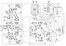
I was comparing his best Goldman to my best "symasym" type voltage stage (CX).
OS
True that both Goldmund and Goldman Sachs know how to extract
money out of thin air....
... I'm here from "other " thread to offer my services , so we can , ofcourse to make an double sided , more compact .....PCB for better designed amplifier . I'm in standby from now .
Regards Alex.")
Glad to have you on board, if you'll excuse the pun.
Here is LTspice schematic of Sentec
/Martti
Sentec had very good reputation
might be among the best of its time
I vote for 4 pairs of outputs and 2SK389 as suggested and keeping ac away from the board. I would also suggest getting rid of the voltage doubler or at least keeping on a different board, maybe a different regulation circuit with a smaller transformer piggy backed on the mail transformer to derive the higher rails for the front end..
Jam
Jam
Last edited:
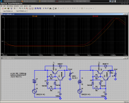
A small issue with the simulation schematic is that the original Goldmund schematic has a 2k7 series resistor in the driver voltage doubler. This will probably drop about 50 volts (assuming 20mA current). This would also imply that the +-80V supply suggested by nagysaudio is higher than what Goldmund originally has. Does not make sense to have lower voltage on the driver rails.
/Martti
Resulting voltage is no more than 70V with 8mA current, wich
is about the one drained by the front end.
Rising time of this voltage is about 10 seconds after power on..
Here the sim for the original PS and for a modded one as well
as the two schematics.
Attachments
Last edited:
wahab,
How about a shunt for the regulator.
Jam
Hi, Jam
It would be useful for a class A amp or a very low noise
preamp, but in that case, PSRR will be good enough with
a classic serial reg.
At 50/60HZ . it is about 94db for the original and 100db
for the modded one.
VAS resistors
QUOTE: Amps with this kind of topology seem to be a fashion at the moment.
This is the first one I see that uses emitter degeneration resistors for the VAS LTP. What's the point doing so?
To increase the linearity of the VAS and to decrease distortion......
regards,
Piersma
QUOTE: Amps with this kind of topology seem to be a fashion at the moment.
This is the first one I see that uses emitter degeneration resistors for the VAS LTP. What's the point doing so?
To increase the linearity of the VAS and to decrease distortion......
regards,
Piersma
This is the first one I see that uses emitter degeneration resistors for the VAS LTP. What's the point doing so?
To increase the linearity of the VAS and to decrease distortion......
Piersma
Not that simple...
Linearity of the VAS increase, but available gain for NFB
decrease as well..
Worse, the gained linearity doesn t manage to compensate
for the said NFB ratio loss, leading to actually higher THD...
Agreed Wahab, but what about the balancing of the diff. pair without the resistors?
regards,
Piersma
If it s the two 75R source resistors, it s not possible
to reduce or suppress them, moreover if high gm fets
like 2SK389 are used, as the circuit would be instable.
Their purpose is not to balance the input stage fets,
but to reduce their transconductance to levels compatible
with a decent stability of the whole circuit..
Hi, Jam
It would be useful for a class A amp or a very low noise
preamp, but in that case, PSRR will be good enough with
a classic serial reg.
At 50/60HZ . it is about 94db for the original and 100db
for the modded one.
My bad...
Figures are 74db and 80db, that is, an order of magnitude
mistake...but still enough considering the amp has large NFB
at these frequencies...
You would be surprised to what a Low Z (sub mOhm) dedicated reg can still subjectively do over basic amp's sonics if incorporated for the non power stages... Don't think in terms of PSRR and ripple. Think stages intermodulation over rising rails Z towards the highs. A parallel reg at such rail levels would add dissipation and complexity maybe many builders would not spare for a benefit they haven't tasted so to trust in, at least use the lower Z, flatter impedance Cmult in line filter you can. Keantoken had a good proposition lately in some thread as I recall. He could scale it up voltage wise maybe.
Attachments
Not that simple...
Linearity of the VAS increase, but available gain for NFB
decrease as well..
Worse, the gained linearity doesn t manage to compensate
for the said NFB ratio loss, leading to actually higher THD...
Thanks. This is about what I expected and simulated.
What if you add a current mirror to the input stage LTP? This adds some more gain to this stage and maybe can compensate for the gain loss in the VAS LTP?
I can't let go the idea since I simulated this for so many hours...
- Home
- Amplifiers
- Solid State
- Goldmund Mods, Improvements, Stability