It's not sounding like such a "little" amp anymore.
Yes , this is a "REAL" amp.
No tiny drivers here
, the driver stage is a 40W amp all by itself.when I build , I will play the drivers DIRECTLY (2-1R resistor) into a pair of speakers !
The big one has a little more room on that 250mm X 76mm PCB. Bigger
driver heatsink + larger driver decoupling caps will go on the "frankenamp"
(5 pair OP).
OS
Is it okay to put a little cap in parallel with the 10R groundlift, say about 100n for treble bypass?
yes , that is a good idea. I used a bypass across the 10R to mitigate PC
power supply noise in an earlier amp project .A .1uf multilayer ceramic was used .
OS
GLA-F "Frankenamp"
Rail bars + large driver caps + more room for driver HS.
As promised...
400 -500 REAL watts.
PS- Andrewlebon made it work on $hit board ... Imagine how it will sing
on these layouts. We are at the level of a $15,000 classe' , minus the "Gold"
rails.
OS
Rail bars + large driver caps + more room for driver HS.
As promised...
400 -500 REAL watts.
PS- Andrewlebon made it work on $hit board ... Imagine how it will sing
on these layouts. We are at the level of a $15,000 classe' , minus the "Gold"
rails.
OS
Attachments
Last edited:
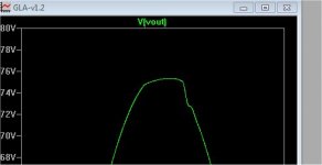
Redo for 85V rails.
85V rails ....
27K/820R for feedback ratio- gain of 30+
2.25V is very low distortion, 2.31V is clip (below 1) @ 151V p-p.
Had to increase the differential gain(s)- 68R emitter resistors , also had to
reduce the lead cap to 6.8pF (below2).
The plot is "reset" to 631K unity gain with 74 degree margin - same as
the little GLA amp (below 3).
OS
Attachments
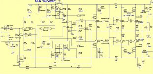
GLA SURVIVOR
PS- Andrewlebon made it work on $hit board ... Imagine how it will sing
on these layouts. We are at the level of a $15,000 classe' ,
Hi Ostripper
greetings i want to make it sing better this amp is it possible to share
pcb layout in pdf so i can use iron transfer pcb method to make pcb if its possible all parts are ready i can finish the amp fast
warm regards
andrew
Only the best for the "builders"
5 pair njw0302/0281 - 2R
run at 50V rails - 400W
njw0302/0281 have low SOA at anything above 60V.
MJL21193/4 are much better.
The MG's by semitech are the "cat's meow" (8R- 600w amp).
GLA with 21193/4's will stand "side by side" with my first creation (badger's).
I'm about to build them both !
OS
5 pair njw0302/0281 - 2R
run at 50V rails - 400W
njw0302/0281 have low SOA at anything above 60V.
MJL21193/4 are much better.
The MG's by semitech are the "cat's meow" (8R- 600w amp).
GLA with 21193/4's will stand "side by side" with my first creation (badger's).
I'm about to build them both !
OS
Hi OS nice work, you seem to have a layout preference (signature). Have also been following this thread http://www.diyaudio.com/forums/solid-state/244892-diamond-differential-amplifier-14.html. It would be nice to have someone compare these amps.
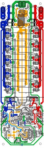
. Have also been following this thread http://www.diyaudio.com/forums/solid-state/244892-diamond-differential-amplifier-14.html. It would be nice to have someone compare these amps.1. - Is the board finished.
2. - Is the signal/power in color - blue =V- red=V+ green=ground(s) yellow=
signal....
3. Is the schema that corresponds to the layout (hopefully -99% ?).
HD pcb bitmap (2100x900) is in the Zip file attached. It should scale to
76mm X 178mm.
OS
The MG's by semitech are the "cat's meow" (8R- 600w amp).
OS
What are MG's by semitech?
What are MG's by semitech?
http://products.semelab-tt.com/pdf/bipolar/MG9410%20MG9410-R.pdf
http://products.semelab-tt.com/pdf/bipolar/MG6330%20MG6330-R.pdf
5 pair of these will boil water with a calrod.
OS
Attachments
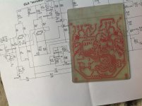
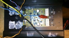
WOW , you move fast.
That is NICE.
You should of added (or asked me , I would of made you a driver board)
with extra pads at the drivers/rail inputs.
I suppose you could just add a few holes at the emitter traces and it
would be good.
Run your V+/V- in at the large traces near C18/19 .
OS
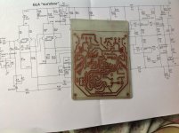
Hi Osstripper
Greetings , is this pcb okay ?
That is NICE.
You should of added (or asked me , I would of made you a driver board)
with extra pads at the drivers/rail inputs.
I suppose you could just add a few holes at the emitter traces and it
would be good.
Run your V+/V- in at the large traces near C18/19 .
OS
http://products.semelab-tt.com/pdf/bipolar/MG9410 MG9410-R.pdf
http://products.semelab-tt.com/pdf/bipolar/MG6330 MG6330-R.pdf
5 pair of these will boil water with a calrod.
OS
Any Spice models available?
Hi OS nice work, you seem to have a layout preference (signature)
I read that thread. They use lag/lead on the dual differential plus miller
comp. on the VAS. NO,no....
Also , the Cascoded VAS is best used with a triple (higher impedance).
They also should reference the VAS cascode to the rails - not ground.
Miller just won't work with this topology. careful choice of the lag/lead
(R8-C5-C6) allows one to "shape" the bode plot. Unity gain freq and at
what point the phase margin "drops off" (heads toward 180deg.) are
very easy to customize.
Sansui used 47R-.0015uF + 10pF for the compensation network with 30
year old parts. (770Khz)
I , to be safe
, slightly increased the margin and lowered the unity gainpoint (630Khz) to ensure stability.
My "layout preference" is quite practical , Keep anything "dirty" away from
anything "clean" (NFB returns + input stages). A super silent - "survivor" amp
will result.
OS
Last edited:
Any Spice models available?
Nope , but the Vsat,hfe vs. Vceo-temp are similar to 21193/4's - just
at double the SOA.
I've seen these used in "pro" amps with typical VFA amplifier topologies.
OS
I read that thread. They use lag/lead on the dual differential plus miller
comp. on the VAS. NO,no....
Also , the Cascoded VAS is best used with a triple (higher impedance).
They also should reference the VAS cascode to the rails - not ground.
Miller just won't work with this topology. careful choice of the lag/lead
(R8-C5-C6) allows one to "shape" the bode plot. Unity gain freq and at
what point the phase margin "drops off" (heads toward 180deg.) are
very easy to customize.
Sansui used 47R-.0015uF + 10pF for the compensation network with 30
year old parts. (770Khz)
I , to be safe
point (630Khz) to ensure stability.
My "layout preference" is quite practical , Keep anything "dirty" away from
anything "clean" (NFB returns + input stages). A super silent - "survivor" amp
will result.
OS
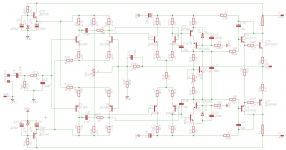
There is no final schematic, just my idea for topology and 'borys' made his working prototype with this schematic (measurements is in post #111)
Attachments
Last edited:
- Home
- Amplifiers
- Solid State
- GLA (good little amp) "survivor"