Well, there ARE limitations to how high the grid 2 voltage can go for pentodes. The max Vg2 specs on the datasheet are too low to use them typically for triodes at face value.
However, the real consideration is how hot the grid 2 gets, or how much current it intercepts times the voltage (now = plate voltage).
Fortunately in triode mode, the plate and grid2 are voltage tracking, and grid 2 intercepts a rather minimal fraction of plate current. (beamers have aligned grids) One can try to estimate the grid 2 heating from the grid 2 current curves (on the pentode curves with Vg2 = Vp), or one can try it out for real. Either measure the grid 2 current and voltage, or watch for grid 2 glowing (worst case, not good! back up some!).
Usually there are some hacker seat of the pants guidelines around for popular TV Sweep tubes. I haven't had any problems on the curve tracer running triode mode on any TV Sweeps. It is probably best to run with the lowest B+ that is practicable, and still giving reasonable distortion, for safety. The high current capability of the TV Sweeps make that quite possible. A tube that can run Amps of plate current can do that easily. You are PAYING FOR BIG HEATER POWER for that current capability, so use it!
The OTs perform better at low primary Z too. The 6LW6 I've heard needs to be careful about max Vg2 in triode. So use one of the $4 tubes, and just try it. (Well, put some fusible, Watt limited, thin-film 10 Ohm resistors in the cathode(s) to protect the OT) It almost certainly will run fine if the max V is kept reasonable and you are operating within the power dissipation specs. Some people around here cannot resist operating well outside the plate dissipation specs! Usually the TV Sweeps will tolerate 30% over dissipation from the spec sheet for audio use, in pentode mode. For triode mode, I would be more careful.
Most DIYers that try the TV Sweeps never go back to Audio tubes. Wonder why.
---
Last edited:
Probably a good idea to put some sort of RC snubber(s) across the B+ to plate primary windings when testing (or always), to protect them if you do arc a tube and blow a cathode fuse. (the back EMF spike from inductance) Of course, always keep a secondary load on the OT.
Deep, or full Class A operation may not be a good idea in triode mode either, if operating anywhere near the max plate Watt specs, since the grid2 will then still be drawing current when the plate/grid2 voltage is well above the B+. So full class A operation should best be kept reasonably below the max Watt specs. (maybe below 70% max Pdiss, someone else might have some guidance on that)
Another thing to keep in mind regarding how sensitive grid 2 is to overheating, is the general rule that you have to trade off 4 plate Watts to gain just 1 grid2 Watt. You can't just sum them up and trade off equal Watts. (some might be tempted otherwise to just add the plate and grid2 Watts off the spec sheet, and call it a triode with that many equivalent plate Watts, not so. 4 to 1)
Last edited:
Just another one to throw into the mix... the 6S19P. It's a true triode, but it needs quite a voltage swing to drive it and its Pa is only 11W. That might be sufficient in P-P though.
On the upside, it's a low voltage, low Ra tube that looks pretty linear, it has no anode top cap, and should be easily and cheaply available in Bulgaria.
On the upside, it's a low voltage, low Ra tube that looks pretty linear, it has no anode top cap, and should be easily and cheaply available in Bulgaria.
Once more the 102 dB
One more thing about Paul Joppa's thumb rule:
I started thinking: Does my own stereo system which I mostly listen to, fulfill the 102 dB requirement by Joppa's thumb rule? Well, it is simple to calculate.
One more thing about Paul Joppa's thumb rule:
I started thinking: Does my own stereo system which I mostly listen to, fulfill the 102 dB requirement by Joppa's thumb rule?
Well, it is simple to calculate. - I know that the loudspeakers' sensitivity is about 85 dB (1 W, 1 m). They were measured when they were new.
- The amplifier is capable to produce 30 W to an 8 ohm load such as my speakers.
- 30 W means 14.8 dB more compared to a 1 W amplifier.
- 85 dB + 14.8 dB = 99.8 dB, which means that my stereo system achieves barely 100 dB, no more (boohoo ).
- That is 2 dB less than Joppa's thumb rule demands. I should have a 50 W amplifier to achieve that 102 dB.
- However, I have not had any problem with power or produced sound pressure.
- At least in my case, 100 dB seems sufficient.
Hi
Hy Girlfriend had decided she wants her own hifi (possible the Wima caps incident - i dont know) and she is starting with the Amp.
So - taking into account my nice new $10k hospital bill - what would be a good, simple, low cost choice for her to start with?
My assumptions are as follows:
Single Ended
Stereo chassis not mono block or twin stereo
We have some fairly sensitive speakers so she is not needing lots of power.
I thought about the GU50 as it is readily available over here, apparently it sounds far nicer in Ultra Linear than Triode so we can get about 6/7W out of it. It does not run at stupid voltage AND it is an unusual looking valve!
But, seriously over here is really well regarded and many prefer it to the 300B.
What do people think and what other options would you people recommend??
You're wrong about ont thing: the GU50 sounds better in triode mode (single-ended). Use one pair (as they are cheap) and get about 7W. You can drive it with another very cheap russian pentode (wired as triode or not). I used a C3g to drive it, but just because I had them at hand, they are expensive.
You're wrong about ont thing: the GU50 sounds better in triode mode (single-ended). Use one pair (as they are cheap) and get about 7W. You can drive it with another very cheap russian pentode (wired as triode or not). I used a C3g to drive it, but just because I had them at hand, they are expensive.
Hi
I have actually been given 4 GU50's (that is how cheap they are - the shops give you them) yesterday - so there is a fair chance of running them in parallel Single Ended.
Do you by any chance have the schismatic for the PSE you built using GU50's - it would be very appreciated.
Fu 50 6J8P 5Z4P Single Ended Tube Amp Amplifier DIY Kit 8W 2 HiFi Design | eBay
They offer power and output transformers, chokes, 120$ extra.
They offer power and output transformers, chokes, 120$ extra.
Fu 50 6J8P 5Z4P Single Ended Tube Amp Amplifier DIY Kit 8W 2 HiFi Design | eBay
They offer power and output transformers, chokes, 120$ extra.
Hi
Thats brilliant - thank you!
I know there will be a million ways this is not sonic'ly the best in the world option but it does offer her the bonus of having (literally) everything she needs in a box - once she has built it and understands how all the components interact she could RE - BUILD it wiring it point to point - etc.
I worked out its a bout $200 for everything including a chassis (which also means i dont have to build a chassis for her).
Personally im dying to build the low voltage amp that someone mentioned with 12 tubes a side - just for the fun of it.
Or 75V B+ with a dozen 12HL7 in parallel. No plate cap either.
gm = 240000 for a dozen of them. Just need a splitter in front.
Id like to build this just for the heck of it - can you point me in the direction of a schematic for this?
Well, you will need a bunch of 12HL7 tubes to select roughly matched ones from, so they run with similar current in parallel connection with the same grid1 bias voltage.
Each bank of tubes gets wired up in parallel (with 5K grid1 stopper resistors for each grid1 to the grid buss, and 1K grid2 stopper resistors similarly for the grid2 to buss). A couple of series'd SS diodes get placed across the final grid1 to cathode buss wires to prevent the grid1 from being pulled positive (anodes toward grid1 buss). (these are frame grid tubes with very tiny grid wires, you don't want to fry them during overdrive conditions) You could put some 100 Ohm film resistors in series with each cathode to buss wire for safety (of the OT) and for measuring idle current when running.
Each bank of tubes gets used like a single tube to wire up a P-P output stage to a suitable OT. Cathode busses grounded. Plate busses connected to the OT primary winding ends. The tubes could be operated in UL or triode mode if the B+ is kept below +150V. Otherwise, use pentode mode with +100V to 150V on the grid2 buss. (these are low screen Volt tubes) Maybe 200V to 300V for B+ on the OT primary center terminal in pentode mode.
The grid1 busses for each bank need to have a negative bias adjuster connected to them (so 2 of them). A 5K pot between -5V and ground should work, with a approx. 90K/n (n = number of tubes in bank) resistor from the pot wiper to the grid1 buss. Put another 20K resistor between -5V and and the pot wiper terminal for safety in case the pot open circuits. (keep tubes from melting down)
Then the grid buss for each bank gets a 1 uF bypass cap connection to the preceding phase splitter stage. The phase splitter could be a Mosfet Concertina stage. It needs to drive a whole bank of grids (especially in triode mode with Miller capacitance issue) so the two load resistors (top and bottom) for the Mosfet need to be low enough to support the current drive requirement, maybe 5K Ohm. The 12HL7 banks will have enormous gm, and will only need a few volts to drive them. So the Splitter only needs to run between + and - 24V rails or so. The Mosfet gate gets a 50K resistor to 1/3 of the way up voltage wise between - and + 24V (bias setting). Then a 0.2 uF cap from the gate to the audio input terminal for DC voltage isolation.
Make sure the OT has a load of some kind for testing.
A further gain stage could be put in front yet for a feedback loop. Global Fdbk to the pre-stage cathode from the secondary to lower gain back down, clean up any distortion and lower the output impedance for speaker damping. A number of other possiblities for "local" feedback around the output tubes, like any other tube amplifier with two output tubes. Some experimenting will be in order once the output stage is functioning.
This was sort of off the napkin so to speak, some refinement might be necessary. So I would just tack solder the prototype together to try this 1st.
Good luck. 12HL7 tubes are $1 at ESRC lately. The 12HL7 is rated for a maximum DC current of 50 mA, so I would set the idle current some where around 15 mA for each, unless running class A P-P, then maybe 45 mA. In class AB, each tube will be swinging between 100 mA and 0 mA (assuming enough B+ and tubes running within Pdiss specs). So n times that for the full bank of tubes. Rough optimum OT primary Z (P to P) for max power would be about 4X (B+ - 50V)/(n x 50 mA)
So 250V B+ and 10 tubes would be 1600 Ohms. The Edcor CXPP25-8-1.6K or a bigger CXPP100-MS-1.7K would fit. 10 tubes in a bank could make serious power out. Higher B+ needs a higher Z OT. Each tube is rated 10 Watt Pdiss, but I would keep that to 7 Watt for tube longevity.
Note, the RCA 12HL7 tubes with the small plates (likely the ones available now) are more like 7 Watt Pdiss, so keep them to 5 Watt. (I would use the smaller Edcor with the smaller tubes, unless you are going to use a lot of them in parallel.) You can still get the bigger Sylvania 10 Watt tubes for around $3 I think.
With a fancier front end (pre-amp stage and differential splitter with Mosfet followers to drive the grid 2 busses) you could use "Crazy Drive" for driving the 12HL7 banks with high linearity. I would get the thing working in the simplest grid 1 drive mode 1st though.
Last edited:
Late edit.
I think one should just use a single SS silicon diode (0.6V) across the cathode to grid1 busses for over-drive protection (anode toward grid1) for each tube bank. The datasheet says +0V max on the grid, so play it safe.
You will want a simple test jig setup to select 12HL7 tubes for similar idle current. Set it up with representative voltages to be used in the amplifier and adjusted for a representative idle current (like 15 mA say). Then run a bunch of tubes through (with fixed bias V and screen V) and select the best matched ones (cathode current, use DVM) for each bank. Just need to be matched within each tube bank, since there are 2 bias adjust pots (one for each bank). Maybe select for a 20% match.
Try and see how it goes, you may have to change the selection criteria if the tubes are scattered badly. I would try to get the same brand and plate style of tubes when ordering them. Probably want to get 50 tubes for two banks of 10. (I have NO idea how the matching will go!)
The alternative is to put bias pots on EACH tube in the tube banks and adjust them all for equal idle current. That will be a lot of work and expense and chassis holes though. But it avoids the matching issue. That's the problem with paralleled tubes.
Last edited:
You got it!!
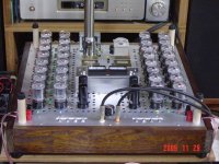
the 12 HeLL 7 amplifier
Maybe should put some Neon bulbs (and series 47K R) across the cathode resistors to indicate tubes that have blown out. Then it will be a redundantly reliable amplifier, you just keep plugging in more tubes as the Neons light up. Well, needs some replaceable fuses, or new film resistors in fuse cartridges, to replace the blown cathode resistors too.
Late edit:
Those cathode resistors need to be more like 10 Ohms (film type) for each tube, otherwise the tube current will be enough to auto-bias them OFF! Such sensitive tubes.
Last edited:
Parallel tube Amps are real. Probably an OTL Amp.
Who needs fireplaces in winter. Maybe they should replace those seasonal fireplace videos (for people without fireplaces) with OTL images. And can you imagine the warm glow (literally) of having an actual OTL amp in ones' home? I can already see myself getting out the marshmellows on a stick. yummm....
Let see, 12 12HL7 per bank, 4 banks for stereo, that's 180 Watts for the heaters. If they were run with low voltage B+, like 75V, that might only be another 2 Watts per tube, so about 300 Watts total heat, for maybe 10 Watts out.
Or running them at full bore, 300V B+, around 7 Watts Pdiss per tube and 3.8 Watts heater per tube, thats about 520 Watts total heat. Yeah, you'll feel the heat from that. But maybe 100 Watts audio output too.
Or running them at full bore, 300V B+, around 7 Watts Pdiss per tube and 3.8 Watts heater per tube, thats about 520 Watts total heat. Yeah, you'll feel the heat from that. But maybe 100 Watts audio output too.
The word boondoggle comes to mind...Let see, 12 12HL7 per bank, 4 banks for stereo, that's 180 Watts for the heaters. If they were run with low voltage B+, like 75V, that might only be another 2 Watts per tube, so about 300 Watts total heat, for maybe 10 Watts out.
10 Watts out
"The word boondoggle comes to mind..."
Its tough to get much power out of tubes with low B+ (like 75V). The typical audio tubes eat 50V to 100V right off the start before even conducting, you are left with whatever is left over for useable B+. The 12HL7 tubes only eat 17.5V. So you can get 10 Watts out with a dozen on each rail at 75V B+. A dozen per rail 12HL7 with 330V B+ can do over 100 Watts output.
That's the boondoggle part - it's a total waste of power, and not even a very good space heater at that.Its tough to get much power out of tubes with low B+ (like 75V).
That's the boondoggle part - it's a total waste of power, and not even a very good space heater at that.
YES - but its fun!
Do you only do things line life because they are sensible?? OH - having been beaten to a pulp and suffered brain damage from it im maybe NOT the best person to follow as a role model but I seriously make an effort NOT to do the sensible thing in place of the FUN thing - Im 45 my GF is 24 - sensible NO - fun YES!
http://www.diyaudio.com//www.pinterest.com/pin/create/extension/
- Status
- This old topic is closed. If you want to reopen this topic, contact a moderator using the "Report Post" button.
- Home
- Amplifiers
- Tubes / Valves
- Girlfriend Wants to Build One