Why 102 dB ?
The earliest text mentioning of that rule I found was from year 1999, but there was no explanation about why 102 dB, not for example 100 dB or 105 dB. Where did he get that number? Why 102 dB ?
Joppa's Rule states that in a listening space of "average" volume an amp/speaker combo should be capable of producing 102 dB. SPL at a 1 meter distance.
The earliest text mentioning of that rule I found was from year 1999, but there was no explanation about why 102 dB, not for example 100 dB or 105 dB. Where did he get that number? Why 102 dB ?
I have no idea where Joppa got the 102 dBspl from, but I notice that OSHA (Occupational Safety and Health Administration) lists 102 db (A scale, slow response, standard sound level meter) as the maximum permissible safe level for 1 1/2 hours each day. I guess so you don't go deaf, like some of those Boom-Boom car drivers who can't hear a Freight Train.
https://www.osha.gov/pls/oshaweb/owadisp.show_document?p_table=STANDARDS&p_id=9735
https://www.osha.gov/pls/oshaweb/owadisp.show_document?p_table=STANDARDS&p_id=9735
Last edited:
Paul Joppa stated 102 dB. SPL peaks, at a 1 meter distance. He did not say you should listen at a 102 dB. level.  It's the transient thing.
Folks, please keep in mind that FAR more speakers have been damaged by underpowered, clipping, amplifiers than have ever been damaged by the application of excessive power.
It's the transient thing.Folks, please keep in mind that FAR more speakers have been damaged by underpowered, clipping, amplifiers than have ever been damaged by the application of excessive power.
FAR more speakers have been damaged by underpowered, clipping, amplifiers than have ever been damaged by the application of excessive power.
In my experience mostly tweeters.
dave
This maybe true with hard clipping SS amplification but is much less likely with soft clipping Valve amplification.Folks, please keep in mind that FAR more speakers have been damaged by underpowered, clipping, amplifiers than have ever been damaged by the application of excessive power.
i don't know why specifically but it is generally said that valve watts are loader than SS watts in terms of human perception. Maybe someone can explain this.
Shoog
OK, sounds reasonable. 1812 Overture "Peaks" safely handled.
------------------
This thread has given me a sense that a "safe" amplifier needs to be developed for the many people who would be reluctant to play with "high" voltages, but would like to DIY a tube Amp. An effort for another thread likely.
Looking through some tube datasheets, I see a simple approach that could be done cheaply, based on a modification of Pete Millett's DCPP amplifier. Which is just a differential front end, with TV tube P-P finals. Lets say 150V B+, which is conveniently available from a cheap 120VAC:120VAC industrial isolation xfmr.
The front end could be 6EW6, 6JC6 or 12HL7 tubes. (12HL7 for driving bigger output tubes like 6HJ5) These are all in the $3 or $4 dollar range. (12HL7 only $1 on sale lately) The output tubes must be plate cap-less and capable of LV high current operation. This would call for a low Zprimary OT, and Edcor has just such an animal, the CXPP25-8-1.6K for $52. Normally low Zprimary would lead to high distortion with small Watt tubes, but the recent "discovery" of "Crazy Drive" allows for a perfect match. Tubes such as 12GE5 (a 6JN6 equivalent), at $3, or 6HJ5, at $4, would fit the bill. Or say 21HB5 (no cap, bigger than 12GE5) or 13GB5 (cheap, but has a cap).
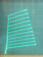
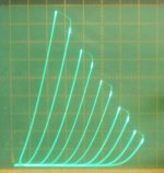
The "Crazy Drive" curves below for the 12GE5 and 6HJ5 show why a low Z primary will work just fine for low distortion here. Only 60V of drive from the front end are required to reach almost 200 mA from the 12GE5 tubes. 6HJ5 is similar, but bigger Watts, and can develop 450 mA with 75V of drive. The "Crazy Drive" curves are so linear, that most ANY load line gives linear results. The 6HJ5 would likely max out the CXPP25-8-1.6K OT using 150V B+. Mosfet followers, or "Power Drive", would be needed to drive the final output screen grids.
One could try Schade "local" feedbacks (like in the original DCPP Amp) to lower the output Z for good damping factor, but likely will need to use plate to driver cathode or driver screen grid (crossed) Fdbks here. (due to 3X lower loop gain around just the final tube with Crazy Drive) 12HL7 are so linear Mu-wise between g2 and g1, that feedback to the g2 would be fine if sufficiently low output Z can be obtained that way. (and no Fdbk caps are needed for the plate to g2 Fdbks)
Crazy Drive curves, 50 mA/div Vert., 50V/div Horiz.
1) 12GE5 (probably 20 mA/div Vert shown here)
2) 6HJ5
3) 21HB5A
4) 13GB5 (has a plate cap)
Another day..... Killer Taxes to do.
------------------
This thread has given me a sense that a "safe" amplifier needs to be developed for the many people who would be reluctant to play with "high" voltages, but would like to DIY a tube Amp. An effort for another thread likely.
Looking through some tube datasheets, I see a simple approach that could be done cheaply, based on a modification of Pete Millett's DCPP amplifier. Which is just a differential front end, with TV tube P-P finals. Lets say 150V B+, which is conveniently available from a cheap 120VAC:120VAC industrial isolation xfmr.
The front end could be 6EW6, 6JC6 or 12HL7 tubes. (12HL7 for driving bigger output tubes like 6HJ5) These are all in the $3 or $4 dollar range. (12HL7 only $1 on sale lately) The output tubes must be plate cap-less and capable of LV high current operation. This would call for a low Zprimary OT, and Edcor has just such an animal, the CXPP25-8-1.6K for $52. Normally low Zprimary would lead to high distortion with small Watt tubes, but the recent "discovery" of "Crazy Drive" allows for a perfect match. Tubes such as 12GE5 (a 6JN6 equivalent), at $3, or 6HJ5, at $4, would fit the bill. Or say 21HB5 (no cap, bigger than 12GE5) or 13GB5 (cheap, but has a cap).
The "Crazy Drive" curves below for the 12GE5 and 6HJ5 show why a low Z primary will work just fine for low distortion here. Only 60V of drive from the front end are required to reach almost 200 mA from the 12GE5 tubes. 6HJ5 is similar, but bigger Watts, and can develop 450 mA with 75V of drive. The "Crazy Drive" curves are so linear, that most ANY load line gives linear results. The 6HJ5 would likely max out the CXPP25-8-1.6K OT using 150V B+. Mosfet followers, or "Power Drive", would be needed to drive the final output screen grids.
One could try Schade "local" feedbacks (like in the original DCPP Amp) to lower the output Z for good damping factor, but likely will need to use plate to driver cathode or driver screen grid (crossed) Fdbks here. (due to 3X lower loop gain around just the final tube with Crazy Drive) 12HL7 are so linear Mu-wise between g2 and g1, that feedback to the g2 would be fine if sufficiently low output Z can be obtained that way. (and no Fdbk caps are needed for the plate to g2 Fdbks)
Crazy Drive curves, 50 mA/div Vert., 50V/div Horiz.
1) 12GE5 (probably 20 mA/div Vert shown here)
2) 6HJ5
3) 21HB5A
4) 13GB5 (has a plate cap)
Another day..... Killer Taxes to do.
Attachments
Last edited:
Distortion that breaks speakers
Suppose an amplifier that distorts sound gently, and produces less high frequencies doing so. That would be quite friendly to the speaker and especially the tweeter. I have heard that such amplifiers actually exist. So perhaps there is a cure to the problem.
Yes, I have heard or read that from many different sources and no doubt that is how things really are. The destruction mechanism as I know goes like this: A speaker is connected to an amplifier that is underrated and is capable to produce low power compared to what the speaker, especially the bass and midrange drivers were rated to. The (boozed) listener plays the small powered amplifier loud, making the last amplifying stage clip the signal as it attempts to exceed the DC rails, which is not possible, and so the signal distorts sharply, containing suddenly plenty of power in high frequencies. The passive crossover filter redirects the high frequency distortion to the tweeter. Such high power in high frequencies is otherwise unusual and the speaker's tweeter was not rated to such high power. So the tweeter breaks. (Someone will notice that after next morning or day.)Paul Joppa stated 102 dB. SPL peaks, at a 1 meter distance. He did not say you should listen at a 102 dB. level.
Folks, please keep in mind that FAR more speakers have been damaged by underpowered, clipping, amplifiers than have ever been damaged by the application of excessive power.
Suppose an amplifier that distorts sound gently, and produces less high frequencies doing so. That would be quite friendly to the speaker and especially the tweeter. I have heard that such amplifiers actually exist. So perhaps there is a cure to the problem.
This maybe true with hard clipping SS amplification but is much less likely with soft clipping Valve amplification.
This is not a clearly valve vrs SS thing. The ACA amps i am using at the moment clip very gracefully.
dave
When a transient clips, it's the difference of simply missing some of the transient, or destabilizing some parts (all?) of the circuit for a number of milliseconds.
First is not really perceived at all (unless very very much of the transient peak is missing), and the second is heard. First as 'tightness' or 'coarseness', then as 'distortion'.
If you must fit the whole height of every transient inside your power reserve, you need a LOT of power reserve. If you only need most of your waveform to fit inside your power reserve (not the transient peaks), you can manage with a lot less.
Yes, I have heard or read that from many different sources and no doubt that is how things really are. The destruction mechanism as I know goes like this: A speaker is connected to an amplifier that is underrated and is capable to produce low power compared to what the speaker, especially the bass and midrange drivers were rated to. The (boozed) listener plays the small powered amplifier loud, making the last amplifying stage clip the signal as it attempts to exceed the DC rails, which is not possible, and so the signal distorts sharply, containing suddenly plenty of power in high frequencies. The passive crossover filter redirects the high frequency distortion to the tweeter. Such high power in high frequencies is otherwise unusual and the speaker's tweeter was not rated to such high power. So the tweeter breaks. (Someone will notice that after next morning or day.)
Suppose an amplifier that distorts sound gently, and produces less high frequencies doing so. That would be quite friendly to the speaker and especially the tweeter. I have heard that such amplifiers actually exist. So perhaps there is a cure to the problem.
this is not the damage mechanism as I have heard it. what happens is as the amp flat lines as it hits the rails it can sink large amounts of current in a virtual DC situation. Continued application of high current DC fries the speakers simply by overheating them. The caps in the cross over are large enough to sustain this flip from DC rail to DC rail for almost constant duty cycle.
Valves are safer for two reasons - they tend to round out rather than go flatline and they are intrinsically more current limiting than overdriven transistors.
Shoog
Crazy Drive is closely related to g2 drive, which is known for running well nearer to class B. (Still waiting for crossover results for Crazy Drive yet)
That would allow one to have high power reserve available, with less idle power/heat. The OT would have to be bigger though to handle the low freq. power peaks. The TV Sweep tubes can readily handle massive peaks. The power supply can still be sized moderately if the LF peaks are not continuous.
That would allow one to have high power reserve available, with less idle power/heat. The OT would have to be bigger though to handle the low freq. power peaks. The TV Sweep tubes can readily handle massive peaks. The power supply can still be sized moderately if the LF peaks are not continuous.
Last edited:
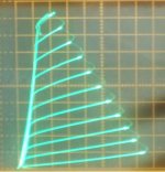
GU-50 is not a low voltage tube. Wavebourn uses a 10K OT with those. If your girlfriend is going to build (and test?) this thing, I would recommend using a tube that will work with LOW LOW voltage (like 200V B+). To do that with some Watts output will take a tube that can handle BIG BIG current. The 36LW6 can do all that and has got way better triode curves than a 300B. 36MC6 and 26LX6/26HU5 are other possibilities.
1) 36LW6
2) 36MC6
3) 26LX6
4) 300B declined to show up
Smoking-amp, I'm interested in possibly using one of the non-overpriced tubes here. I can't locate any tube data on any of them, the most important being MU in triode mode using normal grid 1 drive. I could compute it from your load lines but I can't read on them what the division markings are? Could you supply them. This is a carryover from my interest in needing a fairly low grid drive requirement voltage gain stage to drive them. Screen drives need not apply.

36LW6 Mu 3.7
no data
36MC6 Mu 4 (I've gotten some of these for $8 on Epay before, the triode curves shown earlier were a selected best triode on the curve tracer, most are like the 6HJ5 curves shown below, same for the 36LW6 and 26LX6, selected)
http://frank.pocnet.net/sheets/049/6/6MC6.pdf
26LX6 Mu 4
http://frank.pocnet.net/sheets/123/2/26LX6.pdf
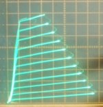
For some cheaper TV Sweep tubes that are fairly good triodes:
6HJ5/6HD5 $4 Mu 4.2 no cap! 24Watt (consistent curves)
http://frank.pocnet.net/sheets/084/6/6HJ5.pdf
http://frank.pocnet.net/sheets/084/6/6HD5.pdf
21LG6A $4 Mu 3.6 28 Watt
http://frank.pocnet.net/sheets/123/6/6LG6.pdf
38HE7 $1 ($0.35 in quantity, no cap) Mu 4.2 nominal 10 Watt (but like 15 Watt if only the pentode running = 21V heater between pins 10 to 12)
http://frank.pocnet.net/sheets/123/3/38HE7.pdf
26DQ5 $3 Mu 3.3
http://frank.pocnet.net/sheets/106/6/6DQ5.pdf
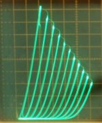
1) 38HE7 in triode 50 mA/div, 50V/div
2) 6HJ5 in triode 50 mA/div, 50V/div
3) 26DQ5 in triode " "
no data
36MC6 Mu 4 (I've gotten some of these for $8 on Epay before, the triode curves shown earlier were a selected best triode on the curve tracer, most are like the 6HJ5 curves shown below, same for the 36LW6 and 26LX6, selected)
http://frank.pocnet.net/sheets/049/6/6MC6.pdf
26LX6 Mu 4
http://frank.pocnet.net/sheets/123/2/26LX6.pdf
For some cheaper TV Sweep tubes that are fairly good triodes:
6HJ5/6HD5 $4 Mu 4.2 no cap! 24Watt (consistent curves)
http://frank.pocnet.net/sheets/084/6/6HJ5.pdf
http://frank.pocnet.net/sheets/084/6/6HD5.pdf
21LG6A $4 Mu 3.6 28 Watt
http://frank.pocnet.net/sheets/123/6/6LG6.pdf
38HE7 $1 ($0.35 in quantity, no cap) Mu 4.2 nominal 10 Watt (but like 15 Watt if only the pentode running = 21V heater between pins 10 to 12)
http://frank.pocnet.net/sheets/123/3/38HE7.pdf
26DQ5 $3 Mu 3.3
http://frank.pocnet.net/sheets/106/6/6DQ5.pdf
1) 38HE7 in triode 50 mA/div, 50V/div
2) 6HJ5 in triode 50 mA/div, 50V/div
3) 26DQ5 in triode " "
Attachments

Last edited:
Thanks a lot smoking-amp! I'm definitely going to investigate this. Without having yet really investigated it seems like those tv tubes are trading MU for transconductance and low rp. So it seems like one "might" be able to get back on the output what you are losing in mu just by employing a much lower turns OT transformer to transform the increased current to the voltage requirement for the speakers. That means a less sophisticated OT also. A win-win. 
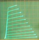
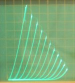
Woops, missed one: 13GB5/EL500/PL500 17 Watt, were $1 on sale, $3 now, Mu approx. 4.8 to 6
http://frank.pocnet.net/sheets/030/p/PL500.pdf
13GB5 in triode, 50 mA/div Vert., 50V/div Horiz., 7 V steps
Oh, and 21HB5A is very close to same as 13GB5 except for compactron base and htr. V, Mu 4.8
http://frank.pocnet.net/sheets/123/2/21HB5A.pdf
were $1 on sale, now $6
http://frank.pocnet.net/sheets/030/p/PL500.pdf
13GB5 in triode, 50 mA/div Vert., 50V/div Horiz., 7 V steps
Oh, and 21HB5A is very close to same as 13GB5 except for compactron base and htr. V, Mu 4.8
http://frank.pocnet.net/sheets/123/2/21HB5A.pdf
were $1 on sale, now $6
Attachments
Last edited:
Apparently I got ahead of myself. Looking at those pdfs you referenced the plate resistances aren't lower than typical tubes. I should have guessed that if this really was some amazing advantage that could be utilized simply on the OT end it would have been glommed onto way before my seeing it. Too bad.
Well, the Rp shown on the pdf's are generally the pentode Rp. Much higher.
The triode Rp can be found from Mu/gm (at the operating current)
For example: for 26LX6
gm at 125 mA is 14000 (microMhos) and Mu is 4 so triode Rp is
10^6 x 4/14000 = 286 Ohms
gm varies roughly as the 0.6666 power of the current (for high gm tubes), for other operating points. So for say 75 mA operation, gm = (75/125)^0.666 times 14000
or 0.71 x 14000 = 9962 leading to a triode Rp of 10^6 x 4/9962 = 401.5 Ohms
for comparison, the 300B has Rp = 700 Ohms at 60 mA (datasheet) or 603 Ohms at 75 mA
The Mu varies some (up slightly) with current too. So Rp is more likely to vary with current as the -0.5 power if you want to compute Rp more accurately in the lower current range. The Mu actually reaches a maximum and then starts to droop down again with really high current, so I usually just use the 0.666 power for a 1st order approx.
Last edited:
Wow!!!
This seems incredible if this is true. Just on the basis of theory maybe one can get back what you are losing in mu by not having to lower the voltage as much in the OT. I still find it hard to believe that these tubes could be overlooked if this is true. It feels a jigsaw puzzle with a missing piece that everyone may have missed for a loooonnnnng time. I'm having a hard believing something so simple might not have been thought of before me. I seems like there must be something me or you are not seeing.
Well, the Rp shown on the pdf's are generally the pentode Rp. Much higher.
The triode Rp can be found from Mu/gm (at the operating current)
For example: for 26LX6
gm at 125 mA is 14000 (microMhos) and Mu is 4 so triode Rp is
10^6 x 4/14000 = 286 Ohms
gm varies roughly as the 0.6666 power of the current (for high gm tubes), for other operating points. So for say 75 mA operation, gm = (75/125)^0.666 times 14000
or 0.71 x 14000 = 9962 leading to a triode Rp of 10^6 x 4/9962 = 401.5 Ohms
for comparison, the 300B has Rp = 700 Ohms at 60 mA (datasheet) or 603 Ohms at 75 mA
This seems incredible if this is true. Just on the basis of theory maybe one can get back what you are losing in mu by not having to lower the voltage as much in the OT. I still find it hard to believe that these tubes could be overlooked if this is true. It feels a jigsaw puzzle with a missing piece that everyone may have missed for a loooonnnnng time. I'm having a hard believing something so simple might not have been thought of before me. I seems like there must be something me or you are not seeing.
- Status
- This old topic is closed. If you want to reopen this topic, contact a moderator using the "Report Post" button.
- Home
- Amplifiers
- Tubes / Valves
- Girlfriend Wants to Build One