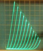
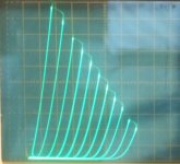
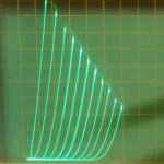
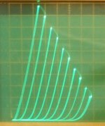
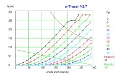
GU-50 is not a low voltage tube. Wavebourn uses a 10K OT with those. If your girlfriend is going to build (and test?) this thing, I would recommend using a tube that will work with LOW LOW voltage (like 200V B+). To do that with some Watts output will take a tube that can handle BIG BIG current. The 36LW6 can do all that and has got way better triode curves than a 300B. 36MC6 and 26LX6/26HU5 are other possibilities.
1) 36LW6
2) 36MC6
3) 26LX6
4) 300B declined to show up
1) 36LW6
2) 36MC6
3) 26LX6
4) 300B declined to show up
Attachments

Last edited:
Paul Joppa has provided us with a useful rule of thumb for matching speakers and amps. Joppa's Rule states that in a listening space of "average" volume an amp/speaker combo should be capable of producing 102 dB. SPL at a 1 meter distance.
Many of us find that rule unreasonable (i am currently happy with 6w -- few of my speakers even reach 90dB). And i have a fairly big room.
dave
6k6 anode to anode seems on the low side; have you done distortion measurements?
Not that low, I've seen several GU50 designs using 5k. The GU50 is pretty similar in it's care and feeding to the KT88 in Triode (aside from the higher grid bias voltage), which they replaced in my amp, and their Ra is lower.
Yes, I did do distortion measurements, but of the whole amp, not just the o/p stage. 2nd Harmonic always dominated - at 1W 1kHz, h2 was -67dB, h3 was -81dB. Output power 9.72W to visible clip threshold (0.3% THD), 15.3W at 5% THD.
This was without Gnfb, just cathode degeneration on the driver stage. It's a differential circuit - 10k input transformer phase splitter followed by 6n2p and 6n1p (-ev) gain and driver stages. It's possible that there may be some distortion cancellation occurring between stages I guess, but that would be a lucky accident.
Output power is clearly fairly modest, but sufficient for my needs, it could be significantly higher of course with fixed bias and class AB operation but was never an aim.
I measure (from the datasheets) for triode mode:
GU-50 Rp = 1430 Ohms at 35 mA
6550/KT88 Rp = 1155 Ohms at 35 mA
using the guide rule of 5X that for low distortion loading, and with Class A and P-P (1/2 x 4) would lead to a 14.3K P-P OT
The 6.6K OT doesn't quite make it.
Now a 26LX6 at 35 mA in triode has Rp = 667 which would work perfectly with the 6.6K OT for P-P class A
But 125 mA (at 200V B+) is more typical for the 26LX6, which would lead to Rp = 286 and a 2.86K OT P-P class A
Last edited:
Isn't the 75 mA for both tubes?
The datasheet says 30 mA max DC for a LS50 in triode class A mode. (it's in German, not sure WHAT is 30 mA)
Anyway, the gm varies approx. as the 0.666 power of current, so 75 mA per tube would lead to 860 Ohm Rp per tube.
And the 3X Rp rule usually gets used for max power (instead of 5X)
so 1430 3X 1/2X 4X goes to 8.58K OT
and 860 3x 1/2X 4X goes to 5.16K OT
http://www.mif.pg.gda.pl/homepages/frank/sheets/043/l/LS50.pdf
Last edited:
No that's 75mA per tube - individual cathode resistors (sorry if the differential description confused) the cathodes are capacitor coupled (as in Allen Wright's DPA-300B design). 860R Ra sounds much more like it in terms of OPT matching.
The GU50 datasheet doesn't contain any equivalent limitation to the LS50 in Class-A. Actually I don't understand why such a limitation would have been specified? - Cathode current is specified at 150mA max, anode dissipation at 40W and G2 dissipation at 5W. Operating at 75mA with 400V B+ is well within these limits (around half). There's a limit of 250V on G2 in pentode (or UL) mode, but in triode, G2 dissipation (measured across the 100R stopper) is very low - around 1W.
It's an extremely rugged tube, (edit: ) especially considering the heavy abuse it would experience in RF PA use.
Last edited:
Can I just put in a vote for using the EL86, or its cheaper sister PL84. These are excellent sounding lowish voltage valves which work well in PP and are cheaper than any EL84.
Shoog
You most certainly can - it was a pair of vintage PSE mono-blocks using EL86 that converted me to tubes 25 years ago! They were absoloulty lovely.
UPDATE
I have just remembered I HAVE the following New Old Stock tubes
JAN GE ECC83 / 12AX7 x 2
JAN GE ECC81 / 12AT7 x 2
On a cost basis it would be good if i could use these in the front end.
I have to say the response has been fantastic and id like to thank everyone - I will have a look at every design offered, there are some that I would like to build myself.......!
UPDATE
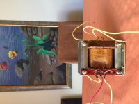
Also found 3 x 100 + 100uf TESLA surface mount capacitors and 4 transformers.
They are soviet "output" transformers - they are to be located close to the speaker originally - in large venues the Russians used amps with no output transformers and ran HT to the speaker where they had the output transformer.
I have no data on these - they are new old stock 1 red wire and 5 yellow.
Pics attached - if anyone can give me a clue on how to obtain the specks on these id be grateful.
Attachments
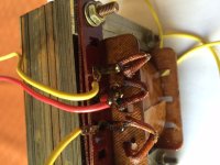
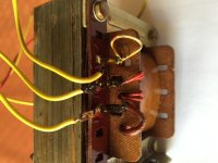
1 look for gap in lamination to determine if SE or (no gap but interleaved E-I cores) PP.
2 measure DC Resistance of windings and make a drawing of them. The low R winding should be the output.
3 apply a small signal to the secondary and measure the output on the primary to get the turns ratio. V out/Vin. Impedance ratio is square of the turns ratio.
2 measure DC Resistance of windings and make a drawing of them. The low R winding should be the output.
3 apply a small signal to the secondary and measure the output on the primary to get the turns ratio. V out/Vin. Impedance ratio is square of the turns ratio.
UPDATE
I have just remembered I HAVE the following New Old Stock tubes
JAN GE ECC83 / 12AX7 x 2
Look for a Magnavox 196 diagram and clone it. You can use the 12AX7 and some JJ EL84 and a 5U4. Use good output transformers and you'll love building it. Simple and sounds great for a 5W SE stereo.
UPDATE
I have just remembered I HAVE the following New Old Stock tubes
JAN GE ECC83 / 12AX7 x 2
JAN GE ECC81 / 12AT7 x 2
On a cost basis it would be good if i could use these in the front end.
I have to say the response has been fantastic and id like to thank everyone - I will have a look at every design offered, there are some that I would like to build myself.......!
The "El Cheapo" I uploaded previously uses 12AT7s in the small signal circuitry.
")
The 12AX7s could go into a phono preamp.
- Status
- This old topic is closed. If you want to reopen this topic, contact a moderator using the "Report Post" button.
- Home
- Amplifiers
- Tubes / Valves
- Girlfriend Wants to Build One