poobah said:Giaime,
If your circuit is making a square wave... that means somewhere there is triangle wave... find it.
This is the first time I hear something like this

what is the technical explanation for that?
Parasitic oscillation shows up as sine wave...
Something must be happening during the flat portion of the squarewave... otherwise it would remain in that state.
You have a sinewave somewhere that is being clipped...
OR
A triangle wave that is causing the square.
Where is your schematic?

Something must be happening during the flat portion of the squarewave... otherwise it would remain in that state.
You have a sinewave somewhere that is being clipped...
OR
A triangle wave that is causing the square.
Where is your schematic?
Giaime said:
... The oscillations stops if I remove ANY of the two plate caps from the 6DQ6 anodes.
Ahhrgh !
You was happy the screens did not blow away

Yves.
I just swapped the anode caps  oscillation resolved!
When I installed the tubes I didn't note that one of the plate caps was going to the screen resistor of the OTHER tube.
Now, another problem:
EL36 are very very unmatched. To get equal currents in the two tubes, the bias voltage has to be about 5V different.
Also bias trimpots are way too hot. Now bias voltage is taken from a 2k2 resistor from high voltage winding, then reverse biased diode, a 33uF cap and 2 50k trimpot to regulate bias for each tube. Each bias voltage then is bypassed by another electrolytic.
Also, if I regulate bias after 5 minutes of operation, and I shut it off and let it cool, when switched on the plate current goes up to the roof...
I will look at servo bias circuits. I was thinking that I need about 55mA for each tube, and if I put it in a 15ohm resistor at the cathode, I get a voltage that's comparable to diode forward voltage. I could put up a simple comparator that regulates bias voltage by comparing voltage across the resistor with a known selected diode...
or other ideas?
I need the bias circuit functioning to define drive requirements. The tube curves suggested a very different bias voltage, much more negative, so if the bias for my EL36s is more positive than expected I could redesign the driver, now needing less volts drive, althought I don't think I'll need much less than 40Vpk swing.
 oscillation resolved!
When I installed the tubes I didn't note that one of the plate caps was going to the screen resistor of the OTHER tube.
Now, another problem:
EL36 are very very unmatched. To get equal currents in the two tubes, the bias voltage has to be about 5V different.
Also bias trimpots are way too hot. Now bias voltage is taken from a 2k2 resistor from high voltage winding, then reverse biased diode, a 33uF cap and 2 50k trimpot to regulate bias for each tube. Each bias voltage then is bypassed by another electrolytic.
Also, if I regulate bias after 5 minutes of operation, and I shut it off and let it cool, when switched on the plate current goes up to the roof...
I will look at servo bias circuits. I was thinking that I need about 55mA for each tube, and if I put it in a 15ohm resistor at the cathode, I get a voltage that's comparable to diode forward voltage. I could put up a simple comparator that regulates bias voltage by comparing voltage across the resistor with a known selected diode...
or other ideas?
I need the bias circuit functioning to define drive requirements. The tube curves suggested a very different bias voltage, much more negative, so if the bias for my EL36s is more positive than expected I could redesign the driver, now needing less volts drive, althought I don't think I'll need much less than 40Vpk swing.
Hi Giaime,
and:
Both is quite strange, lots of (previously unused) PL36/EL36 I had on the bench (guaranteed to be from different plant) did show quite uniform performance after, say 24 hours of simmering at about 50% Pd to burn them in. Also, they didn´t drift much between cold and hot state. Others reported good conformance to the plate curve plots, too.
Before that, I would consider auto bias. Or mixed auto/fixed bias.
Tom
EL36 are very very unmatched. To get equal currents in the two tubes, the bias voltage has to be about 5V different.
and:
Also, if I regulate bias after 5 minutes of operation, and I shut it off and let it cool, when switched on the plate current goes up to the roof...
Both is quite strange, lots of (previously unused) PL36/EL36 I had on the bench (guaranteed to be from different plant) did show quite uniform performance after, say 24 hours of simmering at about 50% Pd to burn them in. Also, they didn´t drift much between cold and hot state. Others reported good conformance to the plate curve plots, too.
I will look at servo bias circuits [....] or other ideas?
Before that, I would consider auto bias. Or mixed auto/fixed bias.
Tom
Yes, I've thought so.
Since tubes are new, probably unusued, I'm planning on cooking them at 50% max plate dissipation for 24H as Tom suggested, by using cathode bias (so I'll be sure that they will never drift and overheat).
Probably my current readings are due to overheating of the trimpots.
Thank you all for help!
Since tubes are new, probably unusued, I'm planning on cooking them at 50% max plate dissipation for 24H as Tom suggested, by using cathode bias (so I'll be sure that they will never drift and overheat).
Probably my current readings are due to overheating of the trimpots.
Thank you all for help!
Aside from those trivial problems  , there's a little thing I thought.
If I take the signal from the two output tube plates, with 1M resistors connected toghether, at the junction of those resistors to a known value resistor to ground (assuming perfectly out of phase signals at the plates and matched resistors) there will be zero volt AC.
However, every imbalance in the push pull will be in the central node as an error signal, ready to be fed back to the first stage unusued negative input.
What do you think of this, has it a name?
Sometimes I have ideas but I don't know yet the theory behind, so...
is it useful? I'm searching for methods of local feedback, since I've got some gain to burn (but not so much that I can eliminate a stage).
Would be better to fed some feedback from the plates of the power tubes to the 5687 driver tubes?
This is because I would like to avoid looping the output transformer in the feedback network, I don't think I'll need it and I'm not technically prepared to deal with it and all the problem associated to a reactive element in a feedback network.
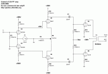
Attached last schematic:
Attachments
Now, I've got a problem. 
I redesigned the driver stages of the EL36 amp, because I was unsatisfied of the results (still not enought drive to the hungry EL36).
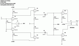
I ended up with this, schematic attached.
However, both TubeCAD and Spice give MUCH MORE output voltage swing and gain than the measured performance on the prototype.
I should have something like 60-70Vrms max output (instead I measure 29Vrms), and 33dB gain (I measured about 28dB).
So what's going on, why do I have those vastly different results?
Keep in mind that voltages here are referred to the prototype I built, which has a recycled power transformer that puts out too low voltage. B+ on the real amp will be at least 300V.
Now I can barely drive EL36 grids that are sitting at -40V, but what about when I'll have them at -50V in the definitive amp? I cannot drive them!
Attached amp schematic:
Attachments
- Status
- This old topic is closed. If you want to reopen this topic, contact a moderator using the "Report Post" button.
- Home
- Amplifiers
- Tubes / Valves
- Giaime's new toy - aka the UniOctal


