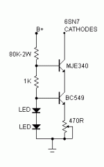
SY said:Planet 10 is about to release CCS boards which would be suitable. Contact him if you want some, or ask him for a schematic. (disclosure: although I helped write the documentation and helped popularize this circuit, I have no financial interest in the sale of these boards) This circuit is stable, easy to adjust, performs superbly, is cheap and easy to build with common parts, and will no doubt end war and famine in years to come.
Thank you very much Stuart. Do you think I can get the schematic and the pcb designs, so I can burn my own pcb's?
I could quibble about adjustment range, but I won't. It should work fine as long as you have at least -10V on the negative supply and that you've designed the negative supply to handle the CCS and reference string currents (not terribly onerous). It will not work tied directly to ground- that only leaves 2V or so for the CCS to operate, much too low.
Valve CCS boards
http://www.diyaudio.com/forums/showthread.php?s=&threadid=72740
I have some of the 1st batch of test boards that can go out, as soon as documents have gone thru one more revision, i'm going to release them and we can get on with a group buy -- hopefully enuff boards to get the board price down quite a bit.
dave
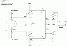
Updated circuit... I think SY meant this:
Edit: how would you see Hammond 1608 output transformers with it? I can get them for 55 euro each. Local winders, even good ones, can give only mediocre transformers for that price... how are they, can they be considered hi-fi with extension up to 20kHz and more?
Edit: how would you see Hammond 1608 output transformers with it? I can get them for 55 euro each. Local winders, even good ones, can give only mediocre transformers for that price... how are they, can they be considered hi-fi with extension up to 20kHz and more?
Attachments
Hello!
Some progress so far.
First, about output transformers, I'm going to try first toroidal mains transformer. See recent thread about parafeed use for them.
I prototyped the first stage of the amp, with the CCS on the bottom (the one 7 posts ago). So, I've discovered an error in the amp schematics: I've done some bad math, because it's impossible to do that with 150V B+. Drop acorss the 10k load resistor is 120V, so 30V for the ECC88 is a bit low. I've raised the B+ up to 200V, I will decide if I'll regulate it, for now is simple RC filter.
The CCS works wonderfully (set to 24mA), I've used 100k as B+ to CCS resistor, BD441 and BC109 as transistors (what I have on my parts bin).
The first stage is putting out some 80Vpp without visible distortion, this with 2Vpp input signal, althought it could do more, I've just ended what my sound card can give as signal generator output.
I'll correct the schematic as soon as I can.
I'm thinking that the gain is too much. I mean, I'll end up with some 0.2Vrms sensibility.
This leaves room to add some local feedback. What's better for you, shunt feedback across the two out-of-phase signals at the grid of the power tubes, or from the anodes of the power tubes to the cathodes of the 5687? In this case, there's a coupling cap in the nfb...
This leaves room to add some local feedback. What's better for you, shunt feedback across the two out-of-phase signals at the grid of the power tubes, or from the anodes of the power tubes to the cathodes of the 5687? In this case, there's a coupling cap in the nfb...
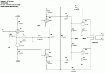
What do you think of this? I took inspiration from the "Baby Huey" amp.
Now, how to determine R7, and connect its value to the actual feedback factor?
From what I understand, R7 and R5 and R8 form a voltage divider that acts only on AC, not on the B+. So it lowers the error signal to the plates of the driver tubes.
Since here the ratio is about 0.27, I understand that the driver tube sees Vplate (of EL36) *0.27 * mu (of EL36) feedback ratio, am I wrong?
With those numbers, I see that I need less than 1/mu feedback ratio, to avoid total degeneration. But Baby Huey uses 0.3 ratio between R5,R8 and R7.
So what?

Attachments
Giaime,
The circuit as shown using the "Baby Huey" inspired shunt feedback will not work as the DC for U3 and U4 are provided via R5 and R8. At the 5687 operating current you will be down to no anode voltage left and the tubes will simply not operate. This is one of the limitations of the Baby Huey method. You need a low current / high rp front end stage for it to work at all.
With the current draw you have set for the ECC88 front end I'm fairly confident you can ditch the second stage altogether, just connect C5 to U1/R1 node and connect C6 to U2/R2 node. That should give you a pretty decent sounding amp and only one phase shifting coupling capacitor to worry about if you want to add a bit of global feedback afterward. An alternative to the ECC88 with this scheme would be a Russian 6H30pi which is a bit gruntier than the ECC88.
Build that and listen for a bit. If the Output Impedance seems a bit high (not enough damping then you can add a bit of global feedback from the secondary to the grid of U2.
If you are short on gain then try the ECC81 as the input stage at a lower current and R1 and R2 increased to say 47K.
If you seriously want to use a "Baby Huey" style circuit go back and look at the schematic I posted for the 6V6 version. Use your original ECC81 choice for the input diffamp (where I used a 6SL7) with the current source at 2.5 mA returned to the bias supply rather than 0V. Use either the 5687's or the ECC88 as a direct coupled cathode follower in place of the MOSFET Source Follower and use the resistor values for the shunt feedback and the ECC81 anode loads as per that schematic.
Hope this is of some help to you.
Cheers,
Ian
Hi Ian,
please remember that Giaime needs about 110-120 Vpp swing for the output stage, this is really hard to do in a single step using a LTP / diff amp. My best bet would be EC91 (high gain like an ECC83, but probably sufficient current capabilities to drive the trioded EL36 w/o slewing) for such a purpose, but sensitivity will be quite low.
It would be a very "forced" thing at the edge, no reserves and all.
Tom
In fact, I haven't found a tube that can do 32dB gain in an LTP and drive output tubes with reasonable impedance. I'd like to make a single stage driver, but it seems I cant't.
This way is also suboptimal, because I'll end up with extreme gain and too much amp sensibility.
I'm thinking to lower R12/R13, and maybe I'll add some global feedback.
This way is also suboptimal, because I'll end up with extreme gain and too much amp sensibility.
I'm thinking to lower R12/R13, and maybe I'll add some global feedback.
In fact, I haven't found a tube that can do 32dB gain in an LTP and drive output tubes with reasonable impedance.
As written above, EC91 can (check out the plate curves, also quite cheap to get, look for CV4070). Okay, "only" 30 or 31 dB, expected swing being 120-130V. Zo would be about 8k or something. A higher B+ of about 400V would be helpful. Still, I wouldn´t recommend it for trioded EL36 (too much on the edge).
Might be quite interesting for trioded EL34 PP, though.
Tom
So I bought 4 EL36, RFT, 5 euro each.
This one:
http://www.jogis-roehrenbude.de/EL34-Story/EL34-Story-Dateien/el36_muehlhsn/Muehlhsn-EL36-1.jpg
However, they oscillate madly.
I put in my old 6DQ6B, and still oscillation.
I can't understand why this happened, nothing changed from the other evening when they were quiet.
I have a strong 50Hz squarewave about 50Vpk at the plates, and at the screens, but nothing on the grid (that stays at -50V). I've added 1k gridstoppers right at the power tubes socket pins, I've removed all the driver circuitry (grid of 6DQ6 now has only the bias voltage), I tried to wind the plate cap wire on a toroid to make an RF choke, still oscillation. The oscillations stops if I remove ANY of the two plate caps from the 6DQ6 anodes.
6DQ6 are trioded with 470ohm g2 stopper: each cathode has 13.8ohm (current sensing) resistor, then to ground. I've tried carefully moving around wires with the unit on, but nothing happened.
Any ideas?

However, they oscillate madly. [....]
I have a strong 50Hz squarewave about 50Vpk at the plates, and at the screens
Extremely unlikely that this is some parasitic oscillations: 50Hz should ring a full Glockenspiel at once.
Tom
Giaime said:It's an oscillation, Tom. Because it starts in high frequencies when the amp is powered on, and when it stabilizes the oscillation comes down to about 50Hz.
Sorry, but you didn´t write this before.
Note that 100uF between g2 and ground stopped it. I'm now increasing g2 stopper resistors, to 1k.
OMG ... welcome to tetrode mode

Tom
- Status
- This old topic is closed. If you want to reopen this topic, contact a moderator using the "Report Post" button.
- Home
- Amplifiers
- Tubes / Valves
- Giaime's new toy - aka the UniOctal


