Giaime,
The direct coupling between stage 1 & 2 forces you to run the first stage plates at a low voltage and the second stage cathodes at a high voltage. Both of these eat up plate to cathode voltage. More plate to cathode voltage is where the tubes generally run more linear.
But, it is all a balancing act...
OOPS... sorry Giaime.
I had to look at your schematic again... the CCS only makes sense on the first stage because it is differential. Forget stages stages 2 & 3.
Dunno about commercial designs... I know that there are some people using large matrices of LEDs for cathode bias as well as ana aternative to resistors and cathode caps.
poobah said:OOPS... sorry Giaime.
I had to look at your schematic again... the CCS only makes sense on the first stage because it is differential. Forget stages stages 2 & 3.
Ah I see. Anyway my mind is now full of differential output stage thoughts
 , but I'd like to keep it simple, a CCS board could be easily fit after.
Should I go for the classical SY's cascode CCS under the first stage? So I can loose the negative supply...
And... what about going differential also for the second stage?
Some thoughts...
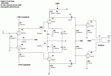
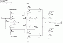
1) all differential IS possible, in terms of gain and availabile B+. But drive capability is small, probably too little. No clear advantages and this big disadvantage, no, it's not the way to go.
2) DC balance: I think that DC balancing the first stage is unnecessary, second stage is a must since it's DC coupled.
3) AC balance: well, why bother balancing the first stage if I can balance both balancing the second one? See attached schematics:
Attachments
The CCS under the first stage will still require a negative supply but your choice of voltage will be easier.
You can go differential on the second stage as well. I can't explain the comparative benefits of that though... Perhaps the benefit would be that you can run CCS on stage 2 as well.

You can go differential on the second stage as well. I can't explain the comparative benefits of that though... Perhaps the benefit would be that you can run CCS on stage 2 as well.
I know that there are some people using large matrices of LEDs for cathode bias as well as ana aternative to resistors and cathode caps.
That's a great idea.
Giame, I would definitely use a CCS in the first stage. The second stage ought to be DC balanced only in the cathode or grid circuit. Lose that plate load pot and just use matched plate resistors.
Sorry for this, but I'm travelling at the moment and can't draw schematics. So I'll have to do this verbally (well, writtenly). I can save you some parts on the second stage and make adjusting easier. Take a pot, connect each end to one of the triodes. Connect the wiper to a single tail resistor to ground. Now you only have to adjust one pot to get balance.
You don't have to bypass there. It's being driven by a differential signal.
For a CCS, my general recommendation is the cascode bipolar that we've been batting around recently.
You don't have to bypass there. It's being driven by a differential signal.
For a CCS, my general recommendation is the cascode bipolar that we've been batting around recently.
SY said:Sorry for this, but I'm travelling at the moment and can't draw schematics. So I'll have to do this verbally (well, writtenly). I can save you some parts on the second stage and make adjusting easier. Take a pot, connect each end to one of the triodes. Connect the wiper to a single tail resistor to ground. Now you only have to adjust one pot to get balance.
You don't have to bypass there. It's being driven by a differential signal.
For a CCS, my general recommendation is the cascode bipolar that we've been batting around recently.
No problem SY, I understood. I have now to search the forum for that cascode bipolar CCS... I recall I have to search in Heretical's threads.
Giaime,
Look at the "heretical line stage" for the proper CCS... There is a good circuit that uses the complemenetary tempco's of the LED and the bipolar for stability. The circuit also uses a buffer transistor to reduce power dissipation (temperature drfit) in the current controlling device (npn).

Look at the "heretical line stage" for the proper CCS... There is a good circuit that uses the complemenetary tempco's of the LED and the bipolar for stability. The circuit also uses a buffer transistor to reduce power dissipation (temperature drfit) in the current controlling device (npn).
I think we're talking about this:
http://home.comcast.net/~syaniger/cf_with_reg_and_servo.gif
So, what are its supply voltage requirements? I see that the psu powers up also the heaters, I guess it's +/- 12V.
What circuit changes are needed to use different transistors? And with those values, can I sink 24mA? I think that this CCS is made to sink much lower currents.
Yep,
That's the one. You may need to adjust resistance values. Transistor selection will be based on power dissipation of the upper device.
I would think you would want at least 12 Volts minimum for the negative supply... you have to consider your maximum swings on the first stage cathodes and insure that you leave at least 2-3 volts, more is better, from C to E on the upper transistor.
Planet 10 is about to release CCS boards which would be suitable. Contact him if you want some, or ask him for a schematic. (disclosure: although I helped write the documentation and helped popularize this circuit, I have no financial interest in the sale of these boards) This circuit is stable, easy to adjust, performs superbly, is cheap and easy to build with common parts, and will no doubt end war and famine in years to come.
SY said:This circuit is stable, easy to adjust, performs superbly, is cheap and easy to build with common parts, and will no doubt end war and famine in years to come.
I can attest to this 100% (well, except maybe the famine part
- Status
- This old topic is closed. If you want to reopen this topic, contact a moderator using the "Report Post" button.
- Home
- Amplifiers
- Tubes / Valves
- Giaime's new toy - aka the UniOctal
 SY????
 Do you really mean to put CCS under output tube's cathodes? Apart from the need of increasing the B+, I understand it's advantages, but I didn't ever saw it in a commercial amp.

