It looks to me and the way he described it that the point Cp is at the centre of the radius of the dome/diaphragm. That means the sound arrives at Cp from all parts at the same time............ as the length from the peripheral phase plug slits is longer then the one in the center,............
The phase error from the midpoints between the slits does introduce an error in timing, but that is inherent in all these slotted/holed plugs. The manufacturer just places the slots close enough to meet their target phase error for the highest frequency they want to pass.
I suspect it's this phase error that causes these CD to lose their flat response in that top octave.
Hi Whgeiger,
Very interesting drawing, but if it near the realty, that would mean, that wave front at the CD mouth is not planar, but spherical, as the length from the peripheral phase plug slits is longer then the one in the center, so may be the horn-throat angle has to be positive, in order that the horn-walls be perpendicular to the wave front.
From Your , attached, drawing it would be possible to get the radius and the center of such spherical surface that would "correspond to the" shape of the wave front.
Regards
Ivica
May be something like this
Ivica
Attachments
May be something like this
Ivica
so Cp' is FROM the driver mouth at the distance dp'=R-sqrt[R^2-(D/2)^2], where R is diaphragm dome radius, and D i driver mouth radius
Ivica
I see it as the other way around, that the slits converge beyond the opening and the wavefront would primarily be concave.as the length from the peripheral phase plug slits is longer then the one in the center,
Perfect ...
... the left leg is supposed to transform a concave wave-front to flat. WHG
I see it as the other way around, that the slits converge beyond the opening and the wavefront would primarily be concave.
... the left leg is supposed to transform a concave wave-front to flat. WHG
No!
Cp - Phase Plug Slit Focal Point
Cd - Spherical Diaphragm Center
The principal reason to make them different is that the diaphragm motion is linear and parallel to the horn axis, not radial as would be generated by pulsating sphere. Thus, the wave pathway vectors are not exactly as you suppose. N.B.: It is a projected area [Sd] that gets you to [Vd] = [X]*[Sd] not the surface area of the diaphragm.
If the phase plug has been properly designed, then only diaphragm breakup modes remain at issue in the highest octave of bandwidth.
WHG
It looks to me and the way he described it that the point Cp is at the centre of the radius of the dome/diaphragm. That means the sound arrives at Cp from all parts at the same time.
The phase error from the midpoints between the slits does introduce an error in timing, but that is inherent in all these slotted/holed plugs. The manufacturer just places the slots close enough to meet their target phase error for the highest frequency they want to pass.
I suspect it's this phase error that causes these CD to lose their flat response in that top octave.
Cp - Phase Plug Slit Focal Point
Cd - Spherical Diaphragm Center
The principal reason to make them different is that the diaphragm motion is linear and parallel to the horn axis, not radial as would be generated by pulsating sphere. Thus, the wave pathway vectors are not exactly as you suppose. N.B.: It is a projected area [Sd] that gets you to [Vd] = [X]*[Sd] not the surface area of the diaphragm.
If the phase plug has been properly designed, then only diaphragm breakup modes remain at issue in the highest octave of bandwidth.
WHG
Last edited:
I reckon I should keep the cross section of the entrance circular until point Cd and from that point outwards shape the Ellipse?
?
What is the horn's mouth shape?
WHG
I reckon I should keep the cross section of the entrance circular until point Cd and from that point outwards shape the Ellipse?
What is the horn's mouth shape?
WHG
The plan was to make an EOS with 90x60 coverage angleWhat is the horn's mouth shape?
WHG
No!
I did not have CAD drawing to work with, so getting beyond a "1st. approximation" is not possible.
[Cp] is a point were the centerlines of the annular passages converge. It is approximate because it was graphically determined.
The profile radius was determined graphically by the intersection of:
1) a normal projected from outer wall of the outer annulus at the point of exit
and
2) a normal projected from the driver/horn axis at the point [Cp]
Note [Cd] was determined graphically as well.
However, the graphic was sufficiently accurate to determine [Cp] (0,0) < [Cd] (Xd,0)
WHG
so Cp' is FROM the driver mouth at the distance dp'=R-sqrt[R^2-(D/2)^2], where R is diaphragm dome radius, and D i driver mouth radius
Ivica
I did not have CAD drawing to work with, so getting beyond a "1st. approximation" is not possible.
[Cp] is a point were the centerlines of the annular passages converge. It is approximate because it was graphically determined.
The profile radius was determined graphically by the intersection of:
1) a normal projected from outer wall of the outer annulus at the point of exit
and
2) a normal projected from the driver/horn axis at the point [Cp]
Note [Cd] was determined graphically as well.
However, the graphic was sufficiently accurate to determine [Cp] (0,0) < [Cd] (Xd,0)
WHG
Ah, I read that wrongly.Cp - Phase Plug Slit Focal Point
Cd - Spherical Diaphragm Center
The principal reason to make them different is that the diaphragm motion is linear and parallel to the horn axis, not radial as would be generated by pulsating sphere. Thus, the wave pathway vectors are not exactly as you suppose. N.B.: It is a projected area [Sd] that gets you to [Vd] = [X]*[Sd] not the surface area of the diaphragm.
If the phase plug has been properly designed, then only diaphragm breakup modes remain at issue in the highest octave of bandwidth.
WHG
It's Cd that is equidistant from the dome/diaphragm
Is this a new phase plug in an existing driver, or a brand new driver with a new phase plug based on your concepts?Attached is a plot of a design that I am working on. Notice that the DI does not change even up to 20 kHz.
Attached is a plot of a design that I am working on. Notice that the DI does not change even up to 20 kHz.
I'm going to speculate on how you did this:
In a one-inch compression driver, the directivity will narrow at 13,500hz. This is because the frequencies above 13,500hz are smaller than the throat of the compression driver.
This generally isn't a concern; I don't think a lot of people are concerned about ultrasonic directivity.
But if you ARE concerned about it, the 'fix' is to use a narrower throat. Probably the easiest and readily available solution is to use a ribbon. For instance, a ribbon that measures 3/4" wide will maintain directivity all the way to 18khz. (13,500 / 3/4" = 18khz)
But you generally don't build waveguides with ribbons, so I'd speculate you're using this to do the job:
An externally hosted image should be here but it was not working when we last tested it.
JBL took a similar approach with their "7 Series." Here's a polar response comparing the JBL M2 with the JBL LSR708i. In the latter speaker, you can see that the beamwidth is constant all the way to 18khz.

JBL M2
An externally hosted image should be here but it was not working when we last tested it.
JBL LSR 708i
Is this a new phase plug in an existing driver, or a brand new driver with a new phase plug based on your concepts?
No new phase plug, newer DE500 driver. It's just proof that the widely held belief below is not actually true.
I'm going to speculate on how you did this:
In a one-inch compression driver, the directivity will narrow at 13,500hz. This is because the frequencies above 13,500hz are smaller than the throat of the compression driver.

See post 7612
Very interesting! So it's the termination of the waveguide that makes a difference.
I pulled up the polars of your old Summa and they seem to exhibit this behavior, IE they're NOT beaming above 13,500hz, while the JBL M2 *is*
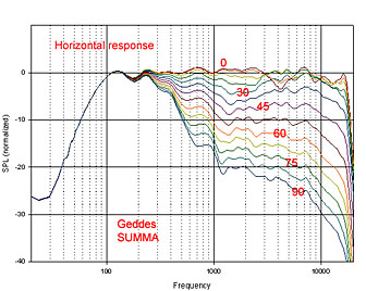
The point is that just because a flat piston on a baffle beams does not means that a waveguide has to beam likewise. They are simply two different mathematical situations.
The systems with the DE250 did beam more than those with the DE500. I suspect that the wave front is closer to flat in the DE500 resulting in a wider CD bandwidth. By the way, the DE500 has the shortest throat of any B&C driver, which may also be a factor.
PS. I am updating your old Summas to the new drivers.
You mean a newer DE500 driver that is already on the market? Is it possible that based on the date of manufacturer, a DE500 may have any one of multiple phase plugs in it?No new phase plug, newer DE500 driver.
Thanks!
- Home
- Loudspeakers
- Multi-Way
- Geddes on Waveguides