Hi Barry.
I suppose you have looked at the 435 driver supplied with Array 1400 and not 2435, the pro version of 435?
The cross sectional drawing of 435's indicates that 435 and 2435 uses the same phase plug geometry.
It's been a while since I really paid attention to these. Yes 435Al (in the 1400 Arrays) and 435Be (project spares) is the designation of the drivers that I have.
I looked in the front of the 1400's with a light and can see a fair amount of the diaphragm through the rings indicating that these are fairly straight.
When I had the Be's apart, from the diaphragm side they look pretty curvy. I don't really want to take them apart again bit I will look at them hard tonight. I do know for sure that they are not simply straight.
Sorry for being imprecise in my writing.
Barry.
Could you elaborate?
I get very good control over 10 kHz with my DE500 drivers, so it's not a given that this needs correction. It would appear that it is a problem with the drivers phase plug, which I would suggest is seldom done correctly.
Hi Gedlee,
As D500 is 1-inch driver, I can imagine (from my experience, and a kind of approximation formula) that You can get quite good dispersion up to about (345/0.0254)*1.1 = 15000Hz
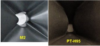
So, for 1.5-inch driver (as 2435), I can imagine that such frequency would be round up to [345/(0.0254*1.5)]*1.1= 10000Hz. If higher frequency would be of interest, then a kind of constriction has to be applied in-order to induce diffraction, but may be such solution is not so nice to for listening, so JBL have introduce more complicated slits shape ( M2, PT-H95 )
On most of the mentioned JBL horns it has been "applied" a kind of about pi/4*D ( D-driver mouth size)
slit in one plane (horizontal or vertical).
JBL M2 has more complicated solution, while on and PT-H95, such has bee applied in one plane, but not a uniform slit, as on the previous solutions (2380, 2360,.....)
Sorry for my bad English.
Regards
ivica
Attachments
Barry,It's been a while since I really paid attention to these. Yes 435Al (in the 1400 Arrays) and 435Be (project spares) is the designation of the drivers that I have.
I looked in the front of the 1400's with a light and can see a fair amount of the diaphragm through the rings indicating that these are fairly straight.
When I had the Be's apart, from the diaphragm side they look pretty curvy. I don't really want to take them apart again bit I will look at them hard tonight. I do know for sure that they are not simply straight.
Sorry for being imprecise in my writing.
Barry.
Did you observe any curvature of the phase plug slits?
You don't need to put effort into this. I reckon you have another project that should be priority

Reverse Engoneering
Here is some 1st. approximation detail.
Regards,
WHG
Thanks whgeiger that's very generous of you. I'm using an Excel spreadsheet for the profile (based on the spreadsheets previously made available by Gedde). I only have to include a round-over to the mouth before I can say it's complete. If you're willing to approbate it when finished, I'd be grateful. Always better to have two set of eyes
You have confirmed my suspicion with the negative angle. The pase plug however do not use fixed angle for the slits. Do you know the optimum WG entrance angle to use with this CD? I believe it would be a compromise regardless?
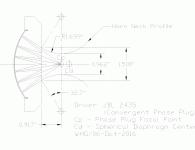
BTW, to my understanding the throat profile lines (vertical + horizontal) would look something like the figure below - example with -15deg entrance for the purpose of illustration
Here is some 1st. approximation detail.
Regards,
WHG
Attachments
Acoustic Speed-Bumps Revisted
For these see earlier in this thread. WHG
http://www.diyaudio.com/forums/multi-way/103872-geddes-waveguides-708.html#post4049190
http://www.diyaudio.com/forums/multi-way/103872-geddes-waveguides-711.html#post4053085
Hi Gedlee,
As D500 is 1-inch driver, I can imagine (from my experience, and a kind of approximation formula) that You can get quite good dispersion up to about (345/0.0254)*1.1 = 15000Hz
So, for 1.5-inch driver (as 2435), I can imagine that such frequency would be round up to [345/(0.0254*1.5)]*1.1= 10000Hz. If higher frequency would be of interest, then a kind of constriction has to be applied in-order to induce diffraction, but may be such solution is not so nice to for listening, so JBL have introduce more complicated slits shape ( M2, PT-H95 )
On most of the mentioned JBL horns it has been "applied" a kind of about pi/4*D ( D-driver mouth size)
slit in one plane (horizontal or vertical).
JBL M2 has more complicated solution, while on and PT-H95, such has bee applied in one plane, but not a uniform slit, as on the previous solutions (2380, 2360,.....)
Sorry for my bad English.
Regards
ivica
For these see earlier in this thread. WHG
http://www.diyaudio.com/forums/multi-way/103872-geddes-waveguides-708.html#post4049190
http://www.diyaudio.com/forums/multi-way/103872-geddes-waveguides-711.html#post4053085
Last edited:
Hi Gedlee,
As D500 is 1-inch driver, I can imagine (from my experience, and a kind of approximation formula) that You can get quite good dispersion up to about (345/0.0254)*1.1 = 15000Hz
Regards
ivica
The idea that a compression driver itself will beam above some frequency is false. If the phase plug is properly designed then there is no theoretical limit to how high the directivity can be controlled.
The idea that a compression driver itself will beam above some frequency is false. If the phase plug is properly designed then there is no theoretical limit to how high the directivity can be controlled.
So, what happens when say a 1" driver plays above 13,500Hz where the wavelength is < 1" or IOW smaller than the aperture (CD throat in this case)? How can there be no beaming in such a case?
So, what happens when say a 1" driver plays above 13,500Hz where the wavelength is < 1" or IOW smaller than the aperture (CD throat in this case)? How can there be no beaming in such a case?
Consider a compression driver on a plane wave tube. Will it ever beam inside the tube? No, it will always cover the interior. Only if the tube is terminated will it beam. It is the termination that causes the beaming not the propagation inside the tube.
Now if the tube is flaring, the interior of the tube is dictated by the wave modes inside the tube and for an OS contour tube these modes do not beam if the throat is feed with the proper wave front. To be precise there is some narrowing of the OS wave functions with frequency, but this effect is very gradual and not nearly as pronounced as a typical piston source on a baffle. The two sets of wave functions are quite different!!
It is the boundary condition of the termination into free space that tends to dictate the pattern NOT the size of the source (for a flat wave front at the aperture into an OS contour.) You would have to go through the math in detail to see this. The fact that my waveguides do not beam significantly even above 10 kHz is supporting data to my claim.
But also what I said before is very true - if the phase plug is not properly designed (i.e. not a flat wave front) then beaming can occur even within the waveguide and as such will continue to beam once the wave front is out in free space. Hence, the only way to get a wide pattern from a poor phase plug is to diffract the wave front near the exit of the CD - but this is because of the phase plug and not because of the size of the aperture.
Last edited:
Thanks a lot WHG, I am grateful for your contribution. I will compare this with the curvature I get from the Excel sheet. I think maybe a 3D print of a scale model will be the next step to consider.Here is some 1st. approximation detail.
Regards,
WHG
Member
Joined 2003
Negative entry angle
Since you guys were discussing negative entry angles, I thought I'd share my experience with the Radian 951Be. Driver is 4"/1.4" with a -7* exit.
Upon seeing the negative exit, I was concerned about throat diffraction. I doubted my ability to build WGs with a negative entry and was also put off by the chances of making "perfect" adapters like Bill's drawing.
My "fix" is based on Earl's work with foam. I tried many ideas but the one that worked was a 1.5" cube of open cell foam in the WG throat right against the CD exit. The foam plugs increased output across the top octave with 20kHz up by 2db. The foam used was "turtle foam" from Amazon. Of course YMMV.
https://www.amazon.com/gp/product/B009KL9KWO/ref=oh_aui_detailpage_o07_s01?ie=UTF8&psc=1
To be precise there is some narrowing of the OS wave functions with frequency, but this effect is very gradual and not nearly as pronounced as a typical piston source on a baffle. The two sets of wave functions are quite different!!
It is the boundary condition of the termination into free space that tends to dictate the pattern NOT the size of the source (for a flat wave front at the aperture into an OS contour.) You would have to go through the math in detail to see this. The fact that my waveguides do not beam significantly even above 10 kHz is supporting data to my claim.
This is a good explanation, thank you. Hadn't considered that in these two cases the math is governed by two different wave functions as you mentioned and assumed that the typical piston source case would apply here as well. I'll agree, your posted measurements do support the theory.
Further, in regards to what you've been able to accomplish based on these measurements and given that the proper waveguide needs to be fed a proper wave-front, it follows that the CD phase plug in this case is a good one. I'll assume it's the DE500. Did B&C design this driver based on your patents or is it just a happy coincidence that it turned out the way it did?
I tried many ideas but the one that worked was a 1.5" cube of open cell foam in the WG throat right against the CD exit. The foam plugs increased output across the top octave with 20kHz up by 2db.
Fascinating, but not quite what I would expect, although I can see how the random scattering of the wave front could tend to average out the variations creating a more uniform one.
When I was working with the foam, I checked for variations in directivity and did not see anything significant at that time. My resolution ability was minimal in the early days and I did not use foam down the throat that far, so I could have missed any effects like that. I clearly did see a loss at 20 kHz from the foam.
Last edited:
The idea that a compression driver itself will beam above some frequency is false. If the phase plug is properly designed then there is no theoretical limit to how high the directivity can be controlled.
Hi Gedlee,
As I said, that is from my own experience, dealing with JBL CD drivers.
May be with some other, as B&C DE500 , just different conclusion can be get.
May be CD designers in JBL had no solutions how to produce 'planar wave front' at CD mouth , or may be they intentionally did not want to produce 'planar wave front' just not to get wide dispersion at higher frequency, or may be they preferred to enhance high frequency dispersion by introducing diffraction in their horn design. If any of our Forum Member has more knowledge or information about that, it would be interesting (for me) to know.
Regards
Ivica
Member
Joined 2003
Paul
In a way, We are saying the same thing. Diffraction generates HOM, which are all variations across the aperture - only the lowest mode is uniform across the aperture. The uniform mode is the most efficient - all HOM as less so. Thus fewer HOM, i.e. less diffraction will do just what we agree is happening. It's just that I would expect some loss due to the internal friction of the foam - this is what is unexpected. Maybe its just too small to have much loss.
In a way, We are saying the same thing. Diffraction generates HOM, which are all variations across the aperture - only the lowest mode is uniform across the aperture. The uniform mode is the most efficient - all HOM as less so. Thus fewer HOM, i.e. less diffraction will do just what we agree is happening. It's just that I would expect some loss due to the internal friction of the foam - this is what is unexpected. Maybe its just too small to have much loss.
The equations in my excel sheet did not match up to the profile you suggested. Can you share your method for the iteration with regards to the curvature?Thanks a lot WHG, I am grateful for your contribution. I will compare this with the curvature I get from the Excel sheet. I think maybe a 3D print of a scale model will be the next step to consider.
1st. Approximation
I simply used a circular arc to demonstrate the concept. I have no specifics on the bounding hyperbola you are using for your horn profile. I positioned the apex on the focal point plane. That may not be the optimum position.
Moving it closer to the plug exit will allow a larger ID at the pinch point. Curvature of the negative leg does not necessarily need to be equal to that of the positive leg. We are simply trying to get rid of the diffraction edge by using a 'gentle' curve. Try to make the curvatures materially match at the apex for both legs. WHG
The equations in my excel sheet did not match up to the profile you suggested. Can you share your method for the iteration with regards to the curvature?
I simply used a circular arc to demonstrate the concept. I have no specifics on the bounding hyperbola you are using for your horn profile. I positioned the apex on the focal point plane. That may not be the optimum position.
Moving it closer to the plug exit will allow a larger ID at the pinch point. Curvature of the negative leg does not necessarily need to be equal to that of the positive leg. We are simply trying to get rid of the diffraction edge by using a 'gentle' curve. Try to make the curvatures materially match at the apex for both legs. WHG
Here is some 1st. approximation detail.
Regards,
WHG
Hi Whgeiger,
Very interesting drawing, but if it near the realty, that would mean, that wave front at the CD mouth is not planar, but spherical, as the length from the peripheral phase plug slits is longer then the one in the center, so may be the horn-throat angle has to be positive, in order that the horn-walls be perpendicular to the wave front.
From Your , attached, drawing it would be possible to get the radius and the center of such spherical surface that would "correspond to the" shape of the wave front.
Regards
Ivica
- Home
- Loudspeakers
- Multi-Way
- Geddes on Waveguides