I must admit to have read only the first couple of dozen pages of this humonguous thread, but I do have a question.
Have you considered gluing a thin layer of foam on the inside surface of the waveguide? Since the undesirable reflections happen there, isn't that the best place to tackle them? Something sound absorbent - cloth, coir, etc. could also be considered.
Have you considered gluing a thin layer of foam on the inside surface of the waveguide? Since the undesirable reflections happen there, isn't that the best place to tackle them? Something sound absorbent - cloth, coir, etc. could also be considered.
I must admit to have read only the first couple of dozen pages of this humonguous thread, but I do have a question.
Have you considered gluing a thin layer of foam on the inside surface of the waveguide? Since the undesirable reflections happen there, isn't that the best place to tackle them? Something sound absorbent - cloth, coir, etc. could also be considered.
For HOMs/reflections I believe the Geddes solution makes more sense- the direct wavefront is largely perpendicular to the walls (and thus minimally affected by a surface treatment). Reflections, if treated similarly to any other reflections, will be at minimum velocity, maximum pressure, at the surface of the horn/waveguide. This is where absorption is least effective. That's why acoustic absorption for room treatment is often spaced a few inches off the surface of the wall or ceiling- it greatly improves efficacy. So filling the horn/waveguide with a low absorption foam plug makes the most sense. Reflections will have to pass through a greater amount of foam due to their path, relative to the direct wave.
Box treatment is similar, with tuned systems you have to be careful not to overdamp the resonant system, but in sealed boxes, it's better to have fill in the middle of the enclosure, rather than lining the walls, assuming suppression of any extra energy is the goal (some people prefer less box damping, probably due to the "live" sound enabled by some stored energy).
Could a cylindrical source be created for crossing to an axissymmetrical waveguide?
Thought one: The difference isn't much and the crossover frequency is low enough to give leeway so just do it.
Thought two: Have this lower frequency source tend from cylindrical to spherical within its upper octave.
Thought three: Avoid early reflections, then trace the two out into the room for the purposes of power matching.
You would have to be clearer on what you mean here. The cylindrical source is LF, below crossover? And it is a finite extent cylinder, not infinite?
A finite height cylindrical source of the right height could be made to match well to a axisymmetric waveguide, but would not in fact be much different than just using a circular woofer as is common.
A cylindrical source is a line source in the vertical direction so in that direction its polar response is going to be nearly identical to a circular piston. Its angular response would depend on its design angle, but below the crossover this is going to be dominated by its width, again just like the circular piston. Hence the difference between the cylindrical and the circular piston in this example is almost nothing. Except that the cylindrical is a lot harder to make work properly. Just use a piston source.
To me, one needs to work the other way around. Not ask: "What will happen if I do this?" but, "This is what I want, how do I get there?" The later is how I designed all of my speakers except that I put constraints on the problem such as size, cost, etc.
The ideal would, of course, be a single driver with constant directivity, but that is not physically possible. Next would be two coincident drivers, but in my experience the implementations of this fail badly at the crossover because the waveguide is too small. Moving the waveguide out of the center of the woofer alleviates many of the crossover problems by using a larger waveguide, but a vertical lobe is inserted. To me, this later tradeoff is by far the easiest to deal with.
Could a cylindrical source be created
Danley Paraline?
still reading the local threads, so far few seem to take advantage of CNC surface profiling, most builds are just stacks of flat sheet with cutouts
but with surface profiling in addition to the planar expansion we should have the possibility of hitting a desired expansion curve like OS (or Hyperbolic for a line source/cylinder wave?)
the bending will still make for reflections, some speculated on adding adsorbing foam
if the internal reflections are geometrically fixed, nulls not too deep, then maybe some ~"Echo Cancellation" FIR in DSP is possible?
Last edited:
One could create a very close approximation to a cylindrical wave even from a compression driver with a proper waveguide design - but only at HFs of course. As the wavelengths become greater than the source dimensions only spherical propagation is possible no matter what you try and do. A dipole being the only exception, but with the drastically falling efficiency that this requires.
FIR cancellation only works at a single point in space. At ALL other points the situation gets worse. One cannot correct a 3D acoustics problem with a 1D electronics solution. It would take a 3D solution to correct a 3D problem.
FIR cancellation only works at a single point in space. At ALL other points the situation gets worse. One cannot correct a 3D acoustics problem with a 1D electronics solution. It would take a 3D solution to correct a 3D problem.
Being the corner sort of guy I am, when I say cylindrical it's more quarter space spherical lemon wedge style. With a 90 degree tweeter waveguide in the way though there are limitations.To me, one needs to work the other way around.
For ~100-700Hz one thought is horizontal 90 degrees across the band and 60 degrees vertical at the top, rectangular pattern, to match power and avoid the floor. Vertical widens to 180 at the low end.
Alternatively 90 degrees circular, widening but limited at the sides. This concerns me as being tricky as I feel I'd rather keep the sides constant.
The thought of cylindrical came from the desire to keep reflections off the floor (30 degrees) down to three hundred and something hertz.
Being the corner sort of guy I am, when I say cylindrical it's more quarter space spherical lemon wedge style. With a 90 degree tweeter waveguide in the way though there are limitations.
For ~100-700Hz one thought is horizontal 90 degrees across the band and 60 degrees vertical at the top, rectangular pattern, to match power and avoid the floor. Vertical widens to 180 at the low end.
Alternatively 90 degrees circular, widening but limited at the sides. This concerns me as being tricky as I feel I'd rather keep the sides constant.
The thought of cylindrical came from the desire to keep reflections off the floor (30 degrees) down to three hundred and something hertz.
I'm not following completely, but controlling directivity to 90 degrees or less below 700 Hz is darn near impossible in a size that would fit a home listening room.
Does what "in one dimension"?
A floor to ceiling line source has no vertical directivity at all unless the floor and ceiling are perfectly absorptive. Theoretically it is a source of infinite length and creates a cylindrical wave that is constant from floor to ceiling. I guess you could call this "directive", but not in the same sense that I think of directing a wave in a free field to a specific location and excluding other directions.
Horizontally it is governed by the same physics that all device must obey.
I'm not following completely, but controlling directivity to 90 degrees or less below 700 Hz is darn near impossible in a size that would fit a home listening room.
I think what he is saying is basically using the room walls as a horn. So basically it is like listening to music right at the mouth of a horn.
Sent from my iPhone using Tapatalk
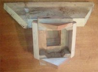
That's right, hence the squared pattern at the sides. I've gone over the theory from all the points of view I can think of. 90 degrees horizontal across the band and the floor bounce mostly managed. I had a renewed interest with the thought of an array/virtual waveguide.
Major issues were fitting the driver as close to the corner as possible without cutting into the drywall and ensuring the wavefront could function as intended. Then there's controlling the mids with the sides walls proper whilst allowing the lows to drop off onto the room walls. Then there's the issue of fitting it under the tweeter and still keeping it off the floor.
The front is baffled into half space (quartered), depends on the point of view for the frequency of interest I guess, but the DI can be made (in theory) to fall gradually and fairly consistently with frequency.
Attachments
I think it fits well.I'm not following completely, but controlling directivity to 90 degrees or less below 700 Hz is darn near impossible in a size that would fit a home listening room.
")
But yeah, it takes up some space.
Attachments
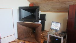
I think it fits well.
But yeah, it takes up some space.
Really!? Photos of setups don't prove anything.
- Home
- Loudspeakers
- Multi-Way
- Geddes on Waveguides