Kindhornman
Actually the term OS completly describes the shape with the addition of a single parameter and that is angle (the throat radius, which is just a scalling value, does not effect the shape), which for my devices is 45 degrees. With that the shape is completly defined. Your question clearly idicates that you have not read any of my work on this subject, which makes it pretty hard to discuss it.
The contour of an OS waveguide is defined by
Y(x) = sqrt( y0^2 + x^2 * Tan(theta0)^2)
Where Y(x) is the radius at any point x along the axis, y0 is the throat radius and theta0 the design angle.
And no my waveguides are not conical, although the OS waveguide does asymptoticly approach conical for large x.
Please read my work first as this will simplify things immensly. It's available for free at Geddes on Audio (chapter 6 of Audio Transducers) so there is no excuse for not reading it.
Last edited:
Winslow,
It is not possible for the input shape to be anything but a circle at the entrance to the waveguide as Earl is using common compression drivers with a round throat exit. The exit of the waveguide and the shape through the cross section is oblate spheroid which just says that it has an elliptical cross section. As I said in my last post a circle is a subset of an ellipse with both axis being equal. So none of this will be determinate of the length of the waveguide or the ratio of the two axis. You could in reality call any conic horn with a round cross section an oblate spheroid, it would meet the mathematical definition.
It is not possible for the input shape to be anything but a circle at the entrance to the waveguide as Earl is using common compression drivers with a round throat exit. The exit of the waveguide and the shape through the cross section is oblate spheroid which just says that it has an elliptical cross section. As I said in my last post a circle is a subset of an ellipse with both axis being equal. So none of this will be determinate of the length of the waveguide or the ratio of the two axis. You could in reality call any conic horn with a round cross section an oblate spheroid, it would meet the mathematical definition.
Earl,
I am just saying semantically that an oblate spheroid can be a circular cross section without a divergent angle from the horizontal to the vertical, at least that will meet the mathematical definition. You are saying that you are using a 45 degree angle and I assume you are saying that this is in the horizontal plane. But that does not mean that the vertical angle can not be set to the same angle which would define a conic shape. I will go back and read that paper but I am just saying you are only using a subset of oblate spheroids by your definition.
I am just saying semantically that an oblate spheroid can be a circular cross section without a divergent angle from the horizontal to the vertical, at least that will meet the mathematical definition. You are saying that you are using a 45 degree angle and I assume you are saying that this is in the horizontal plane. But that does not mean that the vertical angle can not be set to the same angle which would define a conic shape. I will go back and read that paper but I am just saying you are only using a subset of oblate spheroids by your definition.
If you are going to continue to use the Horn equation then you are going to have to defend it. Thats the way of the world.
I think that you will find that defending it will be very difficult, because it is wrong, we all know its wrong and continuing to use it is wrong. Surely you must see that.
Its time to get on the right side of this debate.
Earl,
You are making many assumptions about what I do and what I think here...
")
I do of course know that the horn equation has severe limitations. That is partly why I have invested many hours in working on BEM and modal methods.
And when it comes to directivity, the horn equation has never claimed to be able to predict it, and I have not seen anyone trying to use it for that purpose either. So for this the horn equation is completely wrong (or perhaps it's more correct to say that it's the wrong equation), since it's an equation that cannot calculate the quantity you are looking for. When I need to calculate directivity, I use BEM or modal methods.
No offense, but my interests are not limited to OS waveguides. And I don't choose my interests or take my positions based on what people tell me to do.
Regards,
Bjørn
Bjorn,
I have quickly browsed through your work. It seems very valuable. With some of the BEM sims I have done using Axidriver, it seems the boundary mess size is important as you have addressed, but through the different methods including Earls approach, none seem to address the fact that these waves under consideration are compression waves, and the compression/expansion factor is not considered. Is this understanding correct?
For some reason my gut feeling is that the constant expansion rate is desirable, but when we consider a finite horn where we need to also design a good termination, then the LeCleach horn termination seem reasonable. Then when we think about the plane wave assumed, it seems too ideal because it can never be reasonable accomplished, even if you use a piston with some slight gap between horn throat, there is still that "step", and special design consideration needs to be taken. Once wee take these restrictions in the real world, things may not look as nice and cozy.
I intend to reinvestigate horns some time later continuing what was done before. I do agree though, that there is more than one way to approach horn design. The condition for best performance can be very specific depending on how the air is pushed down the horn.
With some of the BEM sims I have done using Axidriver, it seems the boundary mesh size is important as you have addressed, but through the different methods including Earls approach, none seem to address the fact that these waves under consideration are compression waves, and the compression/expansion factor is not considered. Is this understanding correct?
Thanks for the kind words.
What do you mean by compression waves in this context? Sound is propagated in air by compression and rarefaction, and this is described by the wave equation. And the wave equation is solved numerically in BEM. Nonlinearities are not taken into account in BEM, though, if that is what you have in mind.
Regards,
Bjørn
Earl,
I am just saying semantically that an oblate spheroid can be a circular cross section without a divergent angle from the horizontal to the vertical, at least that will meet the mathematical definition.
You misunderstand what Oblate Spheroidal means. It is a 3 dimensional coordinate system not a shape, so you are using the wrong mathematical definition.
Earl,You misunderstand what Oblate Spheroidal means. It is a 3 dimensional coordinate system not a shape, so you are using the wrong mathematical definition.
In your book, chapter -6- WAVEGUIDES
CONTROLLING SOUND RADIATION
there are pictures of a conical waveguide (Figure 6-2), a simple waveguide broken into sections (Figure 6-13), a typical diffraction horn (Figure 6-23), but no pictures of an oblate spheroidal waveguide.
A picture of one would be worth several thousand words defining the 3 dimensional coordinate system.
Art
Good point. There is a drawing in my first paper on the subject which is in AES.
Consider the elliptical 2D layout, this is shown in my book, but not in Chapter 6 I am afraid. Take an axis normal to the short line origin. Rotate the entire set of curves about this axis and you have the OS coordinate system.
Pick one of the angular radial lines (45 degrees in my case) and rotate this about the same axis defined above and you have the shell of an OS waveguide.
Plot out the above equation and you have the same thing.
Real waveguides are of course of finite length and as such need a flare at the mouth to reduce truncation effects.
OS WG shape is also just a rotated hyperbola. In fact the equation above is equation of hyperbola.
An "elliptic hyperboloid of one sheet" as you call it in English.
Like this: File:Ruled hyperboloid.jpg - Wikipedia, the free encyclopedia (cut it horizontally in the middle, where the throat will be)
An "elliptic hyperboloid of one sheet" as you call it in English.
Like this: File:Ruled hyperboloid.jpg - Wikipedia, the free encyclopedia (cut it horizontally in the middle, where the throat will be)
Yes, that is correct, the curve of the shell cross-section is a hyperbola.
Interestingly enough the OS shell is also a catenoid of minimum surface area connecting two disks. It is the shape that a soap bubble would take between these two surfaces. I always found this aspect interesting.
Interestingly enough the OS shell is also a catenoid of minimum surface area connecting two disks. It is the shape that a soap bubble would take between these two surfaces. I always found this aspect interesting.

I think that you are pointing out that OS is the coordinate system which defines the surface, where the surface is an "elliptic hyperboloid of one sheet" and its cross sectional curve is a hyperbola.
Maybe they should be called Elliptic Hyperboloid Waveguides instead - a rose by any other name ...
Maybe they should be called Elliptic Hyperboloid Waveguides instead - a rose by any other name ...
I just wanted to show this shape as something that everyone probably already knows from some basic geometry and to show the way how it can also be imagined. The name isn't really importnant. So it isn't "something conical" attached to "something round" as someone mentioned earlier... It's really a pretty basic and "simple" surface ("nice" for a mathematician).
Last edited:
As I understand it, in most cases a compression driver is used, this means that the wave is already in a compressed media/state at the throat, whereas assuming a plane wave at the throat seems to indicate that the initial condition of the wave is not a compressed. When you have a compression driver, the low frequency is modulating the total pressure and density, and the high frequency is actually like it's traveling through a media of varying density with time. So you never really get the realistic initial condition.Thanks for the kind words.
What do you mean by compression waves in this context? Sound is propagated in air by compression and rarefaction, and this is described by the wave equation. And the wave equation is solved numerically in BEM. Nonlinearities are not taken into account in BEM, though, if that is what you have in mind.
Regards,
Bjørn
I may be wrong though, but I think all you math wizards probably know the equations more thoroughly that I. But this is the main reason I tend to shy away from compression drivers in home application.
It's really a pretty basic and "simple" surface ("nice" for a mathematician).
Yes, except that it does not "fit" very well into the horn equation - it does not allow for a "nice", "simple" closed form solution as so many of the other shapes do. That is why it was avoided for so long. And the wave functions in this "nice" shape are exceedingly difficult to calculate. So it is visually "nice" and "simple" but a real pain to actually work with.
Earl,
In your book, chapter -6- WAVEGUIDES
CONTROLLING SOUND RADIATION
there are pictures of a conical waveguide (Figure 6-2), a simple waveguide broken into sections (Figure 6-13), a typical diffraction horn (Figure 6-23), but no pictures of an oblate spheroidal waveguide.
A picture of one would be worth several thousand words defining the 3 dimensional coordinate system.
Art
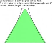
This is a good visual comparison of a conical against an OS curve, albeit not in three dimensions. This illustration was done (I believe) by another diyaudio member, Patrick Bateman.
Attachments
It's simply like this:
The red dots are the cone, that the WG is asymptotically passing to - it defines its radiating angle. These are the asymptotes of the hyperbola.
An externally hosted image should be here but it was not working when we last tested it.
The red dots are the cone, that the WG is asymptotically passing to - it defines its radiating angle. These are the asymptotes of the hyperbola.
Last edited:
- Home
- Loudspeakers
- Multi-Way
- Geddes on Waveguides