Vent holes in horn.
No, these are definitely not entrance holes for mid range. I had a long discussion with him, but thought it a bit too nosey to ask about details of the concept behind the holes. The mids are separately horn loaded. This is not a Marukami US4437540 type of horn. The EV example is nothing like it.
Iain.
If my guess is right, Michael O'Neil may have mis-stated himself or may be getting misquoted- sure looks like a unity horn arrangement to me. Those holes are entrances for midrange speakers.
No, these are definitely not entrance holes for mid range. I had a long discussion with him, but thought it a bit too nosey to ask about details of the concept behind the holes. The mids are separately horn loaded. This is not a Marukami US4437540 type of horn. The EV example is nothing like it.
Iain.


Hi,
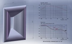
Just saw something at PLASA trade show(Pro Audio, Lighting etc) I had never seen before. Holes in the side wall of a horn, "to relieve back pressure on the returning wave". If it had been anybody other than Michael O'Neil of One Systems (ex of Electrovoice) I would have passed it off as "sales talk". But I went over to the EV stand, and they also had some new product with holes in similar places. Below is a drawing from EV with holes clearly shown. Any thoughts on the theory behind this? In the one systems product it is not on a coax system.
Iain.
View attachment 188397
Thanks for sharing - those holes are an interesting thing - though the "back wave (looped refelctions) reduction effect" IMO is the same sales speak as you now read that EV-horn's are actually "wave guides" from now on.
In a few years we possibly will read EV, JBL etc. are no longer producing "horns" nor "wave guides" but "diffraction alignment device" or whatever is hyped then
LOL
As its a coax construct, there is also low frequency content entering in the area of the HF horn - this may have even more audible impact than what they claim for advertising reasons.
Michael
Last edited:
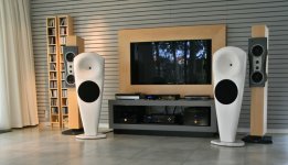
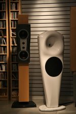
VERY nice!
Now that you have them with Dynaudio speakers, what about some listening impression/comparison?
Room was above 60m2, highly reflective (windows everywhere) with slight echo. Tonality from Dynaudio was ok, nothing disturbing even closely miked female vocals but cymbals, brass in general lacks energy - I didn't hear percussion from Esotar tweeters, sound without life. Mummies were oversharp (albeit have falling HF response between 20-30deg) and of course lacked last octave. I'll double check everything again and wait for opinion of foam plug on the same WG. Fiberglass was damped with polymer coating. In the same time I'm building two way JMLC horn setup and dipolar AMT waveguide (Gauss type) - then we can make finial comparison.
Attachments
Last edited:
Any thoughts on waveguides designed to operate in a 90 corner?
My motivation is that I have a rather small room to be used for home theater. Getting the speakers a fair distance away from the walls as recommended by Dr. Geddes and others may be quite difficult. However, the front walls and corners themselves are clutter free simple planes, so naturally it comes to mind to try to integrate the waveguide into the corner somehow. This would be somewhat similar to what Patrick Bateman has experimented with in his in car unities.
In order to fit the drivers, etc, the waveguide itself would have to be slightly wider dispersion than a conical 90 horizontally, producing a discontinuity. Alternately you could have a waveguide that looks more like the prolate spheroidal coordinate system, which we know from Dr. Geddes is undesirable.
Another approach might be to treat the corner as a 1/4 space waveguide, make the speaker itself as small as possible and concentrate on smoothing the vertical discontinuity where the baffle meets the corner top and bottom. I'm visualizing something like a sphere intersecting the corner with fillets.
I don't think that I ever said that, in fact, in my book I point out that the Prolate Spheriodal is a "perfect" shape, just as the Oblate Spheriodal is. I also point out what the throat configuration needs to be, and in one of my patents I show how one can create precisely this throat configuration. So I would not throw out Prolate Spheriodal, I have used it before.Alternately you could have a waveguide that looks more like the prolate spheroidal coordinate system, which we know from Dr. Geddes is undesirable.
If the directivity is such that it is less than 90 degerees then corner or free space is basically the same. Think of a flashlight of 90 degrees pointing out from the corner. It doesn't see the walls so their being there or not makes no difference.Another approach might be to treat the corner as a 1/4 space waveguide, make the speaker itself as small as possible and concentrate on smoothing the vertical discontinuity where the baffle meets the corner top and bottom. I'm visualizing something like a sphere intersecting the corner with fillets.
jason_watkins, have you seen this thread? http://www.diyaudio.com/forums/multi-way/121385-loudspeakers-room-system-2.html#post1505832
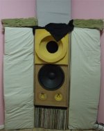
I too want to stay in the corners. I have flanked my speakers with 16" wide absorbers. The total width is around 50" in the corners and I suspect this is closer than recommended...but the improvements brought about by reducing reflections and by bass trapping are well worth it.
Here is a photo (with drapes removed).
Attachments
Dr Geddes,
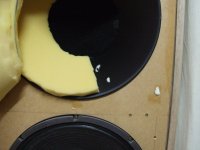
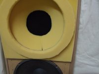
I have used closed cell foam in an attempt to sculpt a mouth termination for my waveguides. These are 90 degrees and 15" at the mouth, and I have fair sized holes in the on axis response.
I am considering using thin rockwool over the baffle around the waveguides. Would it be worth doing?
I have used closed cell foam in an attempt to sculpt a mouth termination for my waveguides. These are 90 degrees and 15" at the mouth, and I have fair sized holes in the on axis response.
I am considering using thin rockwool over the baffle around the waveguides. Would it be worth doing?
Attachments
Dr Geddes,
I have used closed cell foam in an attempt to sculpt a mouth termination for my waveguides. These are 90 degrees and 15" at the mouth, and I have fair sized holes in the on axis response.
I am considering using thin rockwool over the baffle around the waveguides. Would it be worth doing?
Usually you'd want to use open cell for this as it'll damp the termination rather than closed cell, which will act like a poor quality rigid termination (rigid as in structural). It'll still smooth ripple but the open cell will do a better job in most instances IMO.
Usually you'd want to use open cell for this as it'll damp the termination rather than closed cell, which will act like a poor quality rigid termination (rigid as in structural). It'll still smooth ripple but the open cell will do a better job in most instances IMO.
Yes, basically closed-cell is a rigid structure to sound waves.
I don't think that I ever said that, in fact, in my book I point out that the Prolate Spheriodal is a "perfect" shape, just as the Oblate Spheriodal is. I also point out what the throat configuration needs to be, and in one of my patents I show how one can create precisely this throat configuration. So I would not throw out Prolate Spheriodal, I have used it before.
Ahh, sorry. I'm still at the beginning of your book. I need a better understanding of the mathematical preliminaries. Do you have any good references for someone who's weak on continuous math in general and knows little of analysis? I've borrowed Vibrations and Waves by French and Mathematical methods in the Physical Sciences by Boas from the girl I'm dating, who happens to have a degree in physics
.The reason I had thought a prolate spheroid was less than ideal was an (mistaken) intuition I'd developed from reading here that the more of the horn the throat could "see", the more internal reflections would form. I see now that's mistaken, and that it's the diffraction generated by the curve that matters.
Ah, this makes complete sense. So the only possible advantage to a 1/4 space design of some sort would be smaller size, likely at the cost of quality. I may continue to look at this approach for the surrounds, since precise imaging matters less and small size would be an advantage.If the directivity is such that it is less than 90 degerees then corner or free space is basically the same. Think of a flashlight of 90 degrees pointing out from the corner. It doesn't see the walls so their being there or not makes no difference.
Last edited:
I've borrowed Vibrations and Waves by French and Mathematical methods in the Physical Sciences by Boas from the girl I'm dating, who happens to have a degree in physics
Ah, here is what you do: You get your girlfriend to read my book and explain it to you. That, of course, will lead to a fight
, but then you get to make up! 
Ah, here is what you do: You get your girlfriend to read my book and explain it to you. That, of course, will lead to a fight
HA!
Sadly, she abandoned physics promptly in grad school once she realized academia wasn't the life for her. Since then life has taken her to vineyards and various other things, so the majority of the mathematics has fallen out of mind (though she does want to get a tattoo of Euler's equation).
Last edited:
HA!
.. so the majority of the mathematics has fallen out of mind (though she does want to get a tattoo of Euler's equation).
Cool !
You girl friends tattoo my be a good starting point for you - *if* you are after a math or physics degree
Way better if you are more after *understanding* whats going on regarding diffraction is to leave all the math to the software programmers – and just look at the outcome of simus and measurements to get a good picture of what actualy happens
Start out here :
http://www.diyaudio.com/forums/multi-way/103872-geddes-waveguides-56.html#post1847931
And continue here :
http://www.diyaudio.com/forums/multi-way/103872-geddes-waveguides-66.html#post1927585
Once you get around to *read* those plots you will realize by comparison that the whole diffraction story is plain simple.
The conclusions are even more simple:
- you cant avoid diffraction
- you have to see/use (any) boundarys as an allignment device
- penality to bad alignment are looped reflections (CMP behaviour creeping in)
Michael
Last edited:
Well, these waveguides have been a revelation to me and I've had an epiphany!
...it's all about in room power response... (OK, so it wasn't my idea )
)
With my current speakers, I am hearing several types of mixing error that I have never heard before. But in contrast...
I used to build speakers with dome tweeters. I did two things differently to everyone else (as far as I knew at the time). One was to use wide front baffles and reject narrow cabinets. The other was to roll off the top end... I never liked the sound of the upper midrange/lower treble with a dome tweeter. The mid on its own was better, but I couldn't run it like that all the time.
Even using ScanSpeak Revelators, which were very nice drivers, I couldn't stand the upper midrange when I crossed over there, but I did prefer the revelator tweeters crossed at 1500Hz with a first order filter.
This was significant, but I misunderstood all of the signs at the time. I thought the large baffle was because I preferred bass over imaging. I suspected the low crossover was a cone breakup thing, and I thought the first order crossover was because crossovers were evil (well maybe they are, but not the way I was thinking).
I went through a full range single driver phase. These are good, and are still my first choice for smaller systems but they were not the answer I was looking for.
Now I realise what it was all about. Directivity. Even more so as I never treated my rooms. The large baffles gave me half space down to 500Hz. The low crossover point avoided mid/woofer beaming and the first order crossover blended the directivity more smoothly. With second order, the tweeter sounded cleaner, but it also sounded more distinct from the woofer, making it clear that it was a different driver. Now, I prefer to go more narrow than half space.
Years of chasing on axis response targets and matching phase to within a hair may have been in vain. I always managed to convince myself somehow that the room didn't matter, but perhaps my efforts with carbon resistors, triode amps and and any other 2nd HD I could get my hands on were an attempt to spread the spectrum a little in order to blur the midrange issues . For my next amp I'll be dumping the carbons, but I might hang on to the triodes .
Back to the mixing errors, I have been hearing passages (the harsh type that usually cause me to clench my ears), and the sound engineer has dialled back the levels for a second...BUT...I cannot hear the harshness with my current speakers and I therefore can't hear the need to drop the levels. I only know from memory that it would have been necessary. Now it sounds strange.
I suspect that the sound engineer was listening using speakers with dome tweeters. This is just a hunch, they may simply have suffered from a pile of intermodulation distortion, or maybe cone breakup. But it may have had to do with the crossover causing the directivity to increase just at the tweeters lower end with a flat on axis response, yet not enough early reflection damping in the room.
I have also heard the engineer pulling back on program peaks (such as where bass lines push the peaks) yet when I listen now, it doesn't seem necessary. It simply causes the song to go quiet for a second.
The thing is that I know the program power (over time) would have sounded consistent on one of my old designs. I wonder how much of this is due to thermal compression issues, how much is due to the peak falling in a high power response region in the mixing speakers, and how much is due to IMD in the mixing speakers. One thing though, I've never heard so many issues in my music, it's becoming quite a concern
...it's all about in room power response... (OK, so it wasn't my idea
)With my current speakers, I am hearing several types of mixing error that I have never heard before. But in contrast...
I used to build speakers with dome tweeters. I did two things differently to everyone else (as far as I knew at the time). One was to use wide front baffles and reject narrow cabinets. The other was to roll off the top end... I never liked the sound of the upper midrange/lower treble with a dome tweeter. The mid on its own was better, but I couldn't run it like that all the time.
Even using ScanSpeak Revelators, which were very nice drivers, I couldn't stand the upper midrange when I crossed over there, but I did prefer the revelator tweeters crossed at 1500Hz with a first order filter.
This was significant, but I misunderstood all of the signs at the time. I thought the large baffle was because I preferred bass over imaging. I suspected the low crossover was a cone breakup thing, and I thought the first order crossover was because crossovers were evil (well maybe they are, but not the way I was thinking).
I went through a full range single driver phase. These are good, and are still my first choice for smaller systems but they were not the answer I was looking for.
Now I realise what it was all about. Directivity. Even more so as I never treated my rooms. The large baffles gave me half space down to 500Hz. The low crossover point avoided mid/woofer beaming and the first order crossover blended the directivity more smoothly. With second order, the tweeter sounded cleaner, but it also sounded more distinct from the woofer, making it clear that it was a different driver. Now, I prefer to go more narrow than half space.
Years of chasing on axis response targets and matching phase to within a hair may have been in vain. I always managed to convince myself somehow that the room didn't matter, but perhaps my efforts with carbon resistors, triode amps and and any other 2nd HD I could get my hands on were an attempt to spread the spectrum a little in order to blur the midrange issues
. For my next amp I'll be dumping the carbons, but I might hang on to the triodes .Back to the mixing errors, I have been hearing passages (the harsh type that usually cause me to clench my ears), and the sound engineer has dialled back the levels for a second...BUT...I cannot hear the harshness with my current speakers and I therefore can't hear the need to drop the levels. I only know from memory that it would have been necessary. Now it sounds strange.
I suspect that the sound engineer was listening using speakers with dome tweeters. This is just a hunch, they may simply have suffered from a pile of intermodulation distortion, or maybe cone breakup. But it may have had to do with the crossover causing the directivity to increase just at the tweeters lower end with a flat on axis response, yet not enough early reflection damping in the room.
I have also heard the engineer pulling back on program peaks (such as where bass lines push the peaks) yet when I listen now, it doesn't seem necessary. It simply causes the song to go quiet for a second.
The thing is that I know the program power (over time) would have sounded consistent on one of my old designs. I wonder how much of this is due to thermal compression issues, how much is due to the peak falling in a high power response region in the mixing speakers, and how much is due to IMD in the mixing speakers. One thing though, I've never heard so many issues in my music, it's becoming quite a concern
What speakers are you actually using? Some pics would help.
Personally I think there might be other reasons causing harshness. For example, a recording of Frutz Kreisler using the Carlo IX violin sounded very harsh. Others also had the same problem with this recording. After tuning my interconnects to provide for constant input impedance, the harshness went away, the whole soundstage was more holographic.
Personally I think there might be other reasons causing harshness. For example, a recording of Frutz Kreisler using the Carlo IX violin sounded very harsh. Others also had the same problem with this recording. After tuning my interconnects to provide for constant input impedance, the harshness went away, the whole soundstage was more holographic.
- Home
- Loudspeakers
- Multi-Way
- Geddes on Waveguides