Hornloading a heil
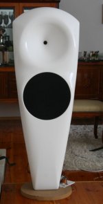
One project I'm working on is a set of horns for Heil AMT1s. Would love some feedback from the good doc. The profile here has been modified, with the MDF roundings flattened to maintain a straight expansion as well as prevent constriction of the wavefront and associated diffraction.
Would love to hear your opinion on how this will operate, Doc. The profile is close to OS (straight wall into a gentle flare at the end) but obviously we're talking about a ribbon source not a round one. Earlier on, there was a post simulating something very similar from Mige0:
Dipole Horn, Dipole Directivity Control Device
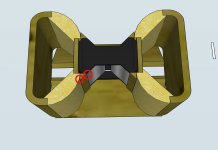
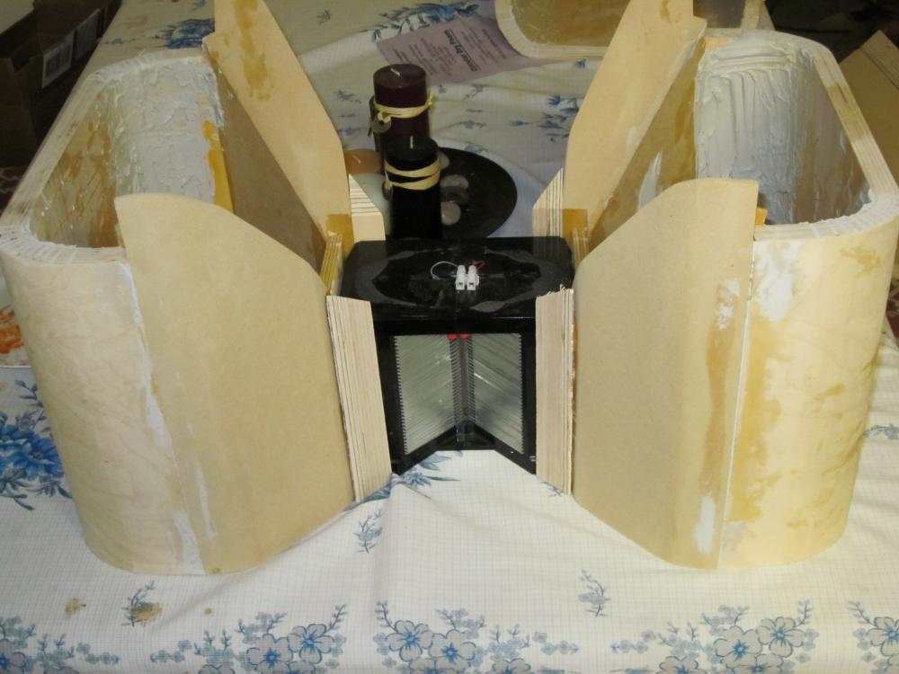
First shot is the underside to help explain assembly, second is as it would look in use. The bottom plane would be the top of the woofer cabinet.
One project I'm working on is a set of horns for Heil AMT1s. Would love some feedback from the good doc. The profile here has been modified, with the MDF roundings flattened to maintain a straight expansion as well as prevent constriction of the wavefront and associated diffraction.
Would love to hear your opinion on how this will operate, Doc. The profile is close to OS (straight wall into a gentle flare at the end) but obviously we're talking about a ribbon source not a round one. Earlier on, there was a post simulating something very similar from Mige0:
Dipole Horn, Dipole Directivity Control Device
An externally hosted image should be here but it was not working when we last tested it.
An externally hosted image should be here but it was not working when we last tested it.
First shot is the underside to help explain assembly, second is as it would look in use. The bottom plane would be the top of the woofer cabinet.
That was an interesting page. I've doodled similar sketches for the Beyma TPL150 monopole for a project later.
The profile beyma uses for their hornloaded version is similar to what I've done- I won't call it OS but that's the closest match, a straightwalled flare with a short roundover termination. Mine wraps around to the rear of course, because it's meant to stand on top of the bass cabinet. The Beyma is intended for baffle mounting. I plan to use some acoustic absorption on the bottom plane (the mounting surface for the AMT) since it's so close and I want to minimize any potential comb filtering.
Surprisingly I cannot damp driver resonances with pad and LCR at the output. Only with a LCR combination at the input and output and only if I find values by trial and error.
If you're willing to throw away some efficiency, the crossover for a compression driver is a lot easier if you include an l-pad in the circuit.
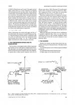
Looks like an ideal case for a Keele CD flare as used in the JBL 2344 (4430 horn). This gave a very consistent 90 degree beamwidth and great polars. You can use the same flare horizontally and vertically, although the ribbon length will preclude getting full beamwidth to a very high frequency.
The text explains the calculation of the flare.
Don't tell Earl!
David Smith
The text explains the calculation of the flare.
Don't tell Earl!
David Smith
Attachments
Cool beans. Yes, my thinking was that it should act very much like an idealized form of the Keele and/or OSWG. I'm not sure whether I'll include the top section or not, given that there's some LF directivity imposed by dipole cancellation and HF directivity imposed by the height of the source, it seems like the horizontals are more critical to include, and the top may not be desirable.
yeah i was at an audio show recently and someone who apparently liked what he was hearing remarked that i must be using a very simple crossover. You could see the disappointment on his face when i told him otherwise. I don't think my speakers sounded quite as good to him after that... But maybe the amp still sounded good.
lol
One project I'm working on is a set of horns for Heil AMT1s. Would love some feedback from the good doc.
...
Would love to hear your opinion on how this will operate, Doc.
.
Understand.
")
I'll keep my mouth shut...
(almost
)Michael
Thanks for the datapoint. Do you think it would be simpler to just buy their flare then when I get around to buying the drivers?The profile beyma uses for their hornloaded version is similar to what I've done- I won't call it OS but that's the closest match, a straightwalled flare with a short roundover termination. Mine wraps around to the rear of course, because it's meant to stand on top of the bass cabinet. The Beyma is intended for baffle mounting. I plan to use some acoustic absorption on the bottom plane (the mounting surface for the AMT) since it's so close and I want to minimize any potential comb filtering.
If you're willing to throw away some efficiency, the crossover for a compression driver is a lot easier if you include an l-pad in the circuit.
It sure flattens that impedance curve. And in a passive crossover, don't you usually want an L-Pad on the horn?
Understand.
I'll keep my mouth shut...
(almost
Michael
No need for that. Your site is interesting in this app. The design for the heils really isn't derived off the known contours, it's just a logical progression thing. I pictured this when I first got them, before I'd ever built a horn. Extending the straight flare and a large(ish) radius roundover makes all the sense in the world.
Thanks for the datapoint. Do you think it would be simpler to just buy their flare then when I get around to buying the drivers?
Up to you. Certainly it seems to be effective for a baffle-mounded system, though I would want a larger horn to run it as low as possible.
Would love to hear your opinion on how this will operate, Doc.
I not a big fan of ribbons, the efficiency is too low and the cost is too high, hence I have never looked into doing anything with them.
As to "Don't tell Earl!", that info is in my book.
I not a big fan of ribbons, the efficiency is too low and the cost is too high, hence I have never looked into doing anything with them.
As to "Don't tell Earl!", that info is in my book.
Certainly the cost is high relative to a compression driver, but there are some pretty significant advantages- one being that the pattern needn't collapse nearly so much as there's no exponential throat, and there's vertical directivity imposed by the dipole cancellation and the transducer size in that dimension.
Am I right in guessing that the secondary flare of the keele type reduces directivity with decreasing frequency, if only slightly?
No need for that. Your site is interesting in this app.
Thanks for the flowers
As Earl is avoiding any response to my statements for some time now, this may become kind a starnge discussion in *his* thread – just in case someone not so familiar with history is scratching his head ...
 LOL
LOL----------
To start with – I'd put it provokative:
„An AMT is just the better compression driver“
What I mean with that is – AMT and compression drivers are basically the same priciple – which most people are not aware of.
*If* we cut an AMT into front and back (avoiding to look at the puzzling dipole behaviour) – and – remove the expansion part of a compression driver phase plug – we see that basically both diaphragms move air out of slits - perpendicular to the movement of the diaphragm.
So, in the most basic way we start out with the same „sound generator“ to feed a horn / waveguide.
Because – as also not everybody is aware of – the expansion part ot the phase plug of a copmression driver already is part of the horn / waveguide rather than part of the „driver“ itself - be it AMT or CD.
Well now, at a first glance this possibly seems not really relating to the questions you might had in mind – but in a more general sense it might justify to discuss your design more deeply *exactly* at this thread.
Michael
Last edited:
Now that we have split the "real driver" ("sound generator") from the horn at the right place we could look at your design where possibly could be seen room for improvement.
As you are certainly aware of, any horn contour that have kinks is sub optimal. This holds true very generally as any kink creates reflections that get looped in the horn and also can not be corrected upstream (EQed) because they happen in time (CMP distortion).
At the first inch of the horn / waveguide there isn't much you can do with both a compression driver or a original Heil.
But then what I'd suggest is simply to remove all kinks of horn / waveguide contour in the first place.
Once you give it a listen, I'm pretty sure you will start to love AMT on horn / waveguide
Keep us updated
Michael
Attachments
Last edited:
Dedicated thread
So as not to rain on the good Dr.'s parade, I've given this a dedicated thread.
http://www.diyaudio.com/forums/planars-exotics/171441-hornloading-heil-amt1.html#post2264863
Mige0: I have already sanded the projecting rounded portions down. When I first looked at the assembly, it seemed like less of an issue than the render (or real life) show. It's been corrected. The intent was always to fill the assembly-to-heil gap with foam window gasketing. The remaining "plywood triangle" to MDF gap is in-process of being filled with Bondo
Last edited:
- Home
- Loudspeakers
- Multi-Way
- Geddes on Waveguides