Count me in on the GB (apparently the WIKI stuff is still not working on the new server) - I registered on the old WIKI for 2 of each.
By the way, IMHO Peter and Uriah did a terrific job on the RevC GB, any advice you get from either of them should be considered GOLDEN.
The new layouts look great.
By the way, IMHO Peter and Uriah did a terrific job on the RevC GB, any advice you get from either of them should be considered GOLDEN.
The new layouts look great.
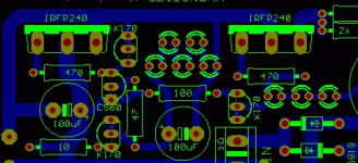
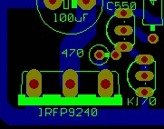
Here is an adjusted layout from PCBCore as sent from Tea-Bag.
Salas,
Looks like the 470 ohm resistor in the middle on the negative rail only has one leg. It appears to have been there in the other doc's as well, on both units.
Tea-Bag
There are 2 470R gate stoppers there. One over the 560, one over the 3 LEDs. I see 2 legs and 2 pads for both. Where it shows?
Opposite side, Do I have my rails messed up?
Small point but I couldn't see a label on the V+, V- and GND inputs. I know you'd figure it very easy from the polarity of the first caps, but if its no hassle, I suggest adding it in. Might save someone a lot of trouble someday!!
Likewise, I am happy to help, but postage from here is no longer cheap. It was upto about a year ago, but no longer. However, if theres anything I can help with, let me know.
Fran
EDIT: only saying this really for the hypnotise as a load of people (or at least so it seemed to me) were going to buy the board for the shunt reg only? Anyway, its only a tiny point
Last edited:
I am here and ready to go with a prototype if you need me. I have 15 tq2 5v relays and one set of matched 2sk107bl and plenty to match more from as well as a few hundred LEDs to match up for that part, I would need to order the rest from mouser but have a BOM waiting so let me know.
Also here for whatever logistical support.
I know that I priced bubbleopes and postage for here in the US and it came out to between $2.50-3.00 per shipment for up to about 4 boards.
Also here for whatever logistical support.
I know that I priced bubbleopes and postage for here in the US and it came out to between $2.50-3.00 per shipment for up to about 4 boards.
Last edited:
Its the same as before plus 1 relay for Hypnotize, plus 2 for Mezmerize if you utilize the full 6 inputs.There were some BOMs compiled I guess. Only you add the two parallel 0.5W resistors (600R in Hypnotize, 300R in Mezmerize) if using NAIS TQ2 5V or just a jumper if with NAIS TQ2-12V. A 2X15V 50VA TX will power the thingies OK. If anybody wants to compile fresh BOMs, look at what the PCBs carry, I attached on #512 http://www.diyaudio.com/forums/showpost.php?p=1908404&postcount=512
The circuits below are the Eagle guides, don't use them directly for BOM, they have some helper equivalent stuff, but good to see the full picture.
Hi Salas, I'm working on both Bom's Mezmerize & Hypnotize.
I'm looking for C7 and IC1 values, haven't found in the schematics.
Hi all, I would definitely go for one of each board, they really look nice, love the layout. How does one "place an order"?
Thanks, Ian.
There used to be a wiki, seems like wikis are not back up on the new improved site yet. Keep an eye on this thread and when the wiki comes back or a new one starts, just add your name and what you want, simple as that.
As promised, Bom's for Hypnotize (Basic) and Mezmerize (Deluxe).
Values are the same for both versions, except one resistor and relays qty :
a) 600R for Hypnotize and 300R for Mezmerize.
b) 1 relay for Hypnotize and 7 for Mezmerize.
As I ignore the real PCB footprint, be carefull with caps lead spacings I specify :
100uF (5mm) - 4700uF(7.5mm) - 100nF (5mm).
For the resistors I've choose 1/2W for all values, without brand information.
I'll just mention that 220R should idealy be "top quality" resistors (cf Salas).
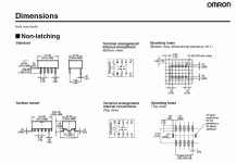
Omron relays specs can be found here :
http://www.components.omron.com/components/web/PDFLIB.nsf/0/DB3627D7D8BCAFF485257201007DD587/$file/G6H_0609.pdf
IC1 is L7812 fixed tension regulator.
C7 is 100nF Metal Film Cap.
Please refer to the PCBs shown here for more informations :
http://www.diyaudio.com/forums/showpost.php?p=1909777&postcount=541
Let me know what should be modified or has been ommited.
Attachments
Last edited:
Hi Salas, May I join the GB? Would you mind ship to Hong Kong area, and how much for the total cost with 4 boards?
Salas is not organizing the GB.
you could be, but I dont know much about relay's here,
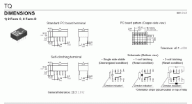
I see that the Omron G6H prototype that crt used as he had it in his device list has the exact same dimensions as the TQ2 we specified because some people already have it. Do you see any possibility for problems?
Omron is fortunately sold by Digikey: http://parts.digikey.com/1/parts/755222-relay-pc-mnt-dpdt-1a-5vdc-g6h-2-100-dc5.html
Attachments
I see that the Omron G6H prototype that crt used as he had it in his device list has the exact same dimensions as the TQ2 we specified because some people already have it. Do you see any possibility for problems?
Omron is fortunately sold by Digikey: http://parts.digikey.com/1/parts/755222-relay-pc-mnt-dpdt-1a-5vdc-g6h-2-100-dc5.html
Do we really need 1/2 watt's everywhere?
Not really, the pads are made wide enough to accept, and that is wise, because a smaller one will go in but not a bulkier one if otherwise. Imagine that some people are gonna use carbon ones for signal passing stoppers like AB, Kiwame, or Dale 1/2W, Shinkoh, etc. Its good to have space. Mind you that the resistors are audible in my B1's audio part. The ones that MUST be 1/2W are the 68R and 600R or 300R. Also the 2K2 for the ''power ON'' LED (this one you can determine by the illumination you want with a given LED in practice).
- Home
- Group Buys
- GB for DC coupled B1 buffer with shunt PSUs
![HYPNOTIZE_IMAGE[1].jpg](/community/data/attachments/130/130496-4a33cfbe398870e222166a9b5e3eb717.jpg)
![MEZMERIZE_IMAGE[1].jpg](/community/data/attachments/130/130507-dcf98491c031016affa487d1e129d7d2.jpg)


